Device for accumulating flat material in flexible strip form

a flexible strip and flat material technology, applied in the field of flat material accumulating in flexible strip form, can solve the problems of increasing the risk of sheath twisting, and achieve the effect of reducing the risk of twisting and poor positioning of the strip

Inactive Publication Date: 2012-09-13
SLEEVER INT
View PDF0 Cites 8 Cited by
  • Summary
  • Abstract
  • Description
  • Claims
  • Application Information

AI Technical Summary

Benefits of technology

[0005]An object of the invention is to provide an accumulator device of the accumulator box type in which the risk of twisting and of poor positioning of the strip is reduced.
[0006]In order to achieve this object, the invention provides a device for accumulating flat material in flexible strip form, the device comprising an accumulator box having a bottom on which the strip accumulates, at least during accumulation stages, between two end walls and between two side walls that extend so as to face edges of the strip, the accumulator device including at least one means for reducing the risk of the strip twisting inside the accumulator box.
[0008]Associating the deflector with means for vibrating the deflector makes it much easier to cause the material to form flat plies, thereby limiting any risk of the flat material twisting, in particular when the material is a ply of heat-shrink plastics material for fabricating heat-shrink sleeves on containers, where such a material is not of uniform thickness and thus inevitably gives rise to problems when traveling through the accumulator box, with a risk of the sheath twisting that is increased in comparison with a flat material that is of uniform thickness. The invention is thus particularly adapted to limiting twisting in such a sheath.
[0014]Various tests have shown that using one or more of these means makes it possible to further decrease the risk of the strip twisting inside the accumulator box.

Problems solved by technology

Associating the deflector with means for vibrating the deflector makes it much easier to cause the material to form flat plies, thereby limiting any risk of the flat material twisting, in particular when the material is a ply of heat-shrink plastics material for fabricating heat-shrink sleeves on containers, where such a material is not of uniform thickness and thus inevitably gives rise to problems when traveling through the accumulator box, with a risk of the sheath twisting that is increased in comparison with a flat material that is of uniform thickness.

Method used


Image

  • Device for accumulating flat material in flexible strip form
  • Device for accumulating flat material in flexible strip form
  • Device for accumulating flat material in flexible strip form

Examples


Embodiment Construction

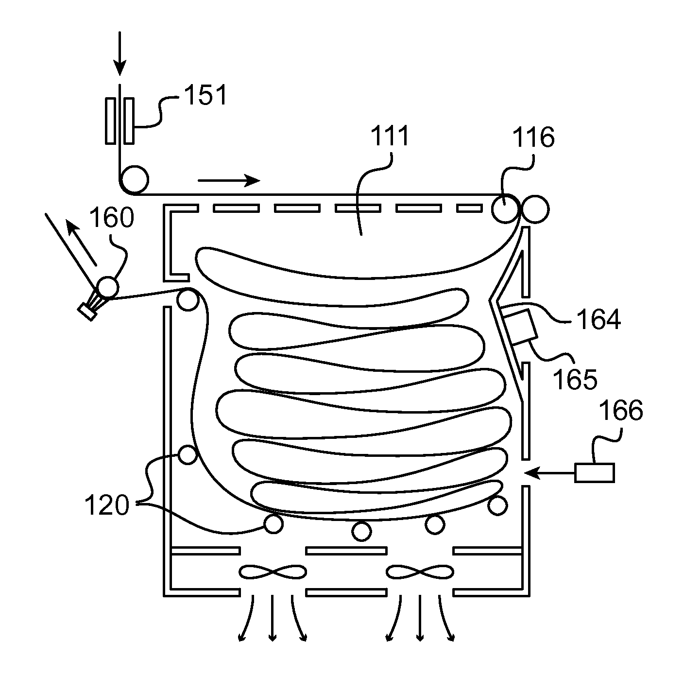
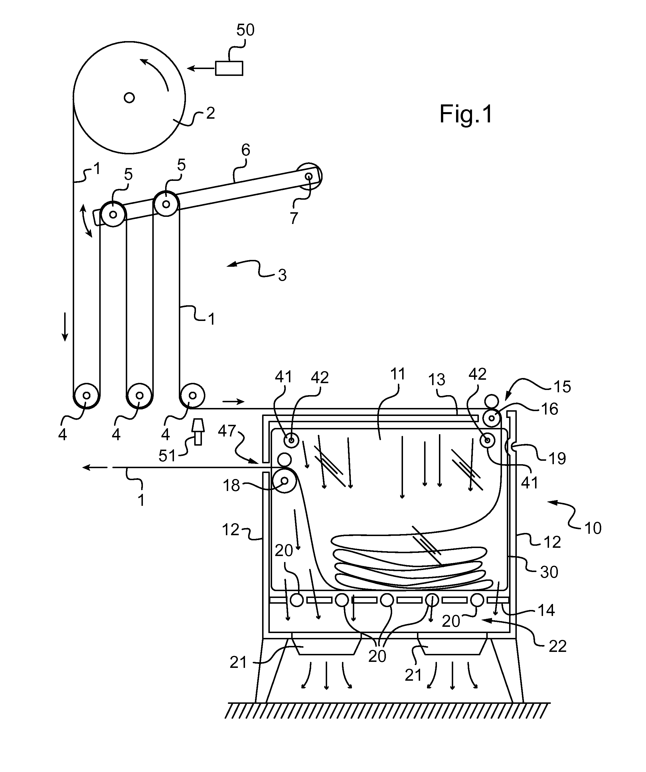
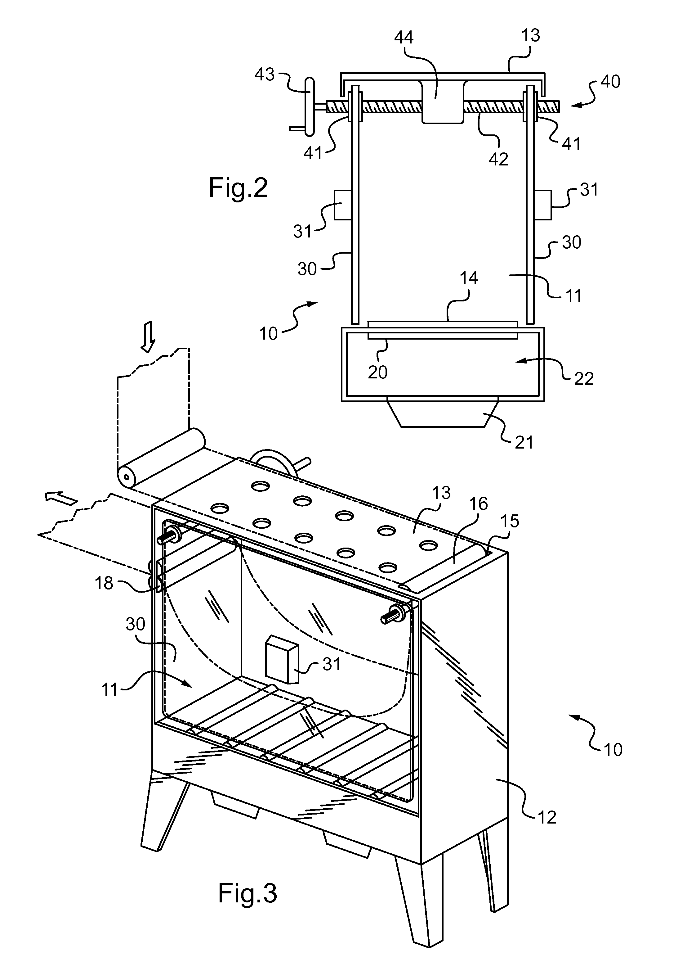
[0021]In a first particular embodiment shown in FIGS. 1 to 3, the accumulator device of the invention is for inserting in an installation that organizes the travel of a flat material in strip form, e.g. a sheath of heat-shrink plastics material. The circuit includes a reel 2 forming a source of strip material 1. The strip 1 is then engaged in a damper device 3 having jumping rollers, comprising a series of stationary rollers 4 and a series of movable rollers 5 mounted on a lever 6 hinged on a pivot 7, with the strip 1 extending between the rollers. The strip 1 is then taken towards an accumulator device 10 of the invention.

[0022]The device comprises an accumulator box 11 with the edges of the end wall 12, of the ceiling 13, and of the bottom 14 being shown in the figure. The accumulator box 11 is also closed by two side walls 30 that can be seen end-on in FIG. 2. In this example, the strip 1 enters into the accumulator box 11 via an opening 15 formed through the ceiling 13, the stri...


PUM


Abstract

The invention relates to a device for accumulating flat material in flexible strip form, the device comprising an accumulator box having a bottom on which the strip accumulates, at least during accumulation stages, between two end walls and between two side walls that extend so as to face edges of the strip. The accumulator device includes at least one of the following means:rollers mounted idle close to the bottom and on which the strip rests during accumulation stages;air-flow means for establishing a flow of air within the box towards the bottom of the accumulator box;vibrator means for vibrating at least one of the side walls; andadjuster means for adjusting spacing between the side walls.

Description

CROSS REFERENCE TO RELATED APPLICATIONS[0001]This application is entitled to the benefit of and incorporates by reference essential subject matter disclosed in French Patent Application No. 11 51982 filed on Mar. 10, 2011.FIELD OF THE INVENTION[0002]The invention relates to a device for accumulating flat material in flexible strip form, e.g. a sheath of heat-shrink plastics material for fabricating heat-shrink sleeves on containers or on any other articles.TECHNOLOGICAL BACKGROUND[0003]In installations for covering containers or other articles in heat-shrink sleeves, it is useful to interpose an accumulator device between the reel carrying a heat-shrink sheath and the station where the sheath is used, with said accumulator device performing several roles. It enables variations in production rates to be absorbed, by avoiding the sheath being pulled too hard. It also enables the reel to be changed while leaving enough time for connecting a new sheath to the end of the old sheath.[0004...

Claims


Application Information

Patent Timeline
Patent Type & Authority Applications(United States)
IPC IPC(8): B65H20/32
CPCB65H20/24B65H20/32B65H2403/60B65H2408/212B65H2408/215B65H2511/12B65H19/14B65H2220/04B65H2220/08B65H2220/11
Inventor FRESNEL, ERIC
Owner SLEEVER INT
Why Eureka
Try Eureka