
Metal cylinder head gasket without a spacing layer

Inactive Publication Date: 2012-09-13
FEDERAL MOGUL SEALING SYST
View PDF2 Cites 1 Cited by
  • Summary
  • Abstract
  • Description
  • Claims
  • Application Information

AI Technical Summary

Benefits of technology

[0017]It is the goal of the present invention to provide a cylinder head gasket with which the uncoiling effect can be reduced. Another object is to provide a cylinder head gasket which has only one functional layer.
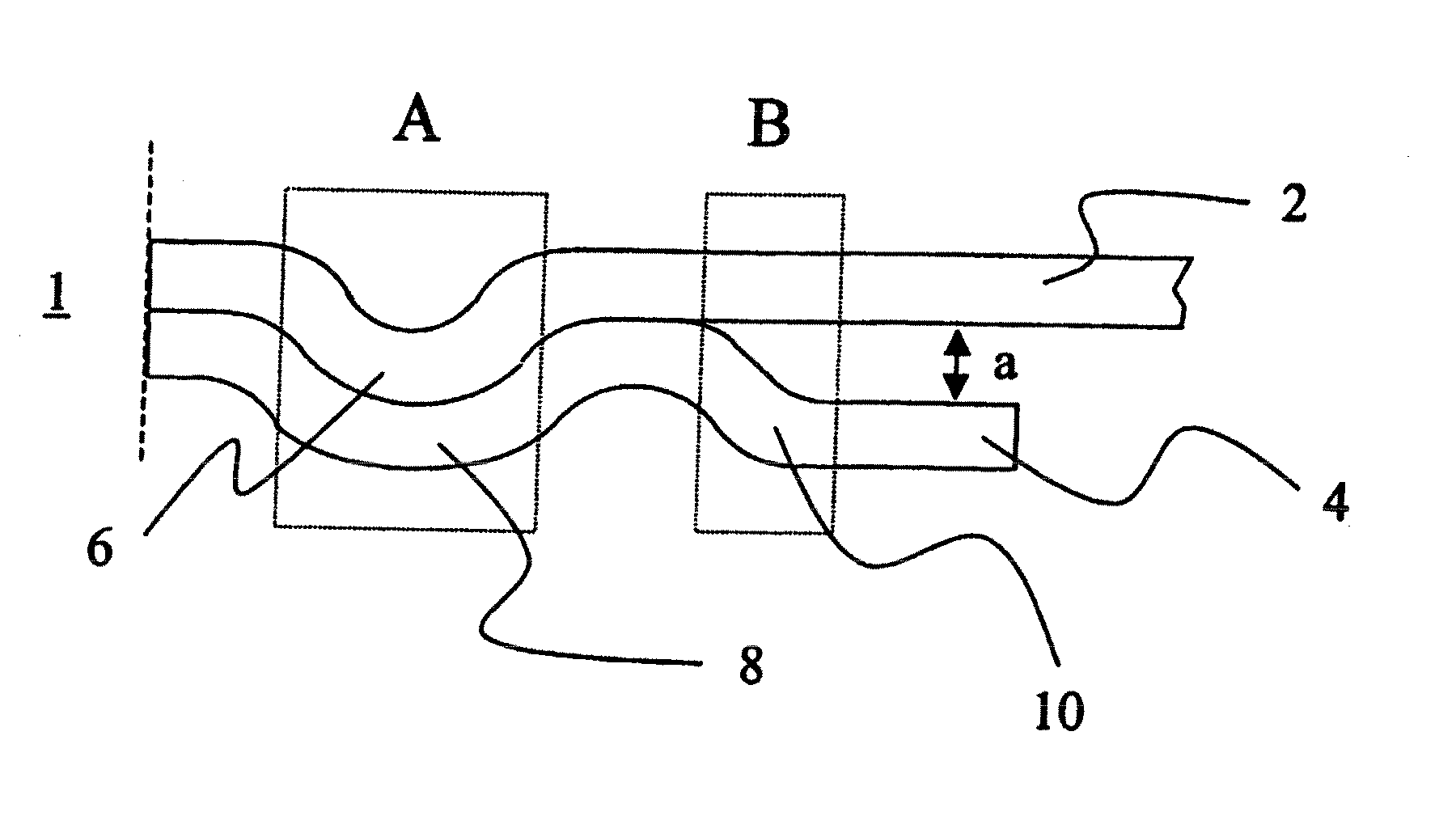
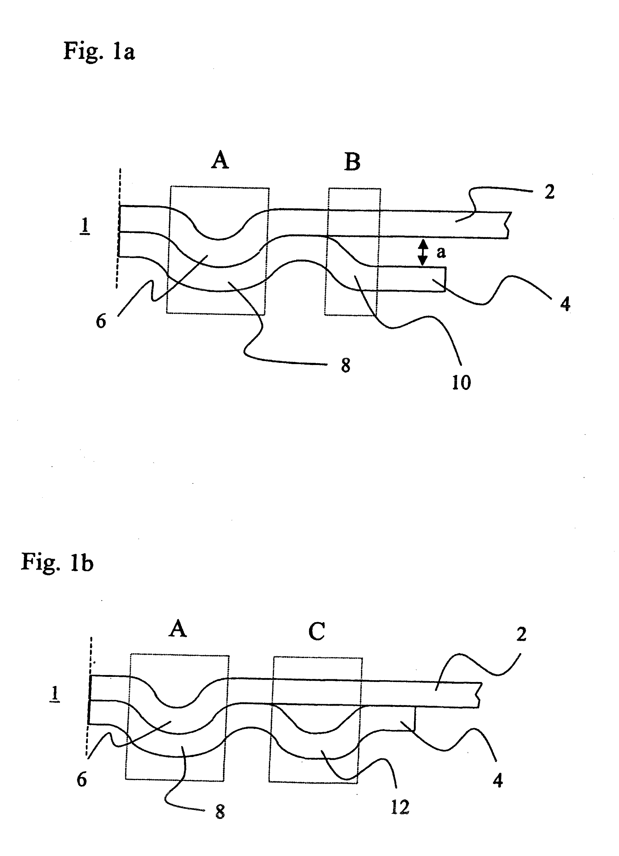
[0028]It is preferred that the support ring extend at least from the bead foot of the full bead, which is next to the combustion chamber, up to the bead foot of the bead, which is next to the combustion chamber. Thereby, a higher rigidity of the gasket is achieved, and the pressure distributes over a larger surface.
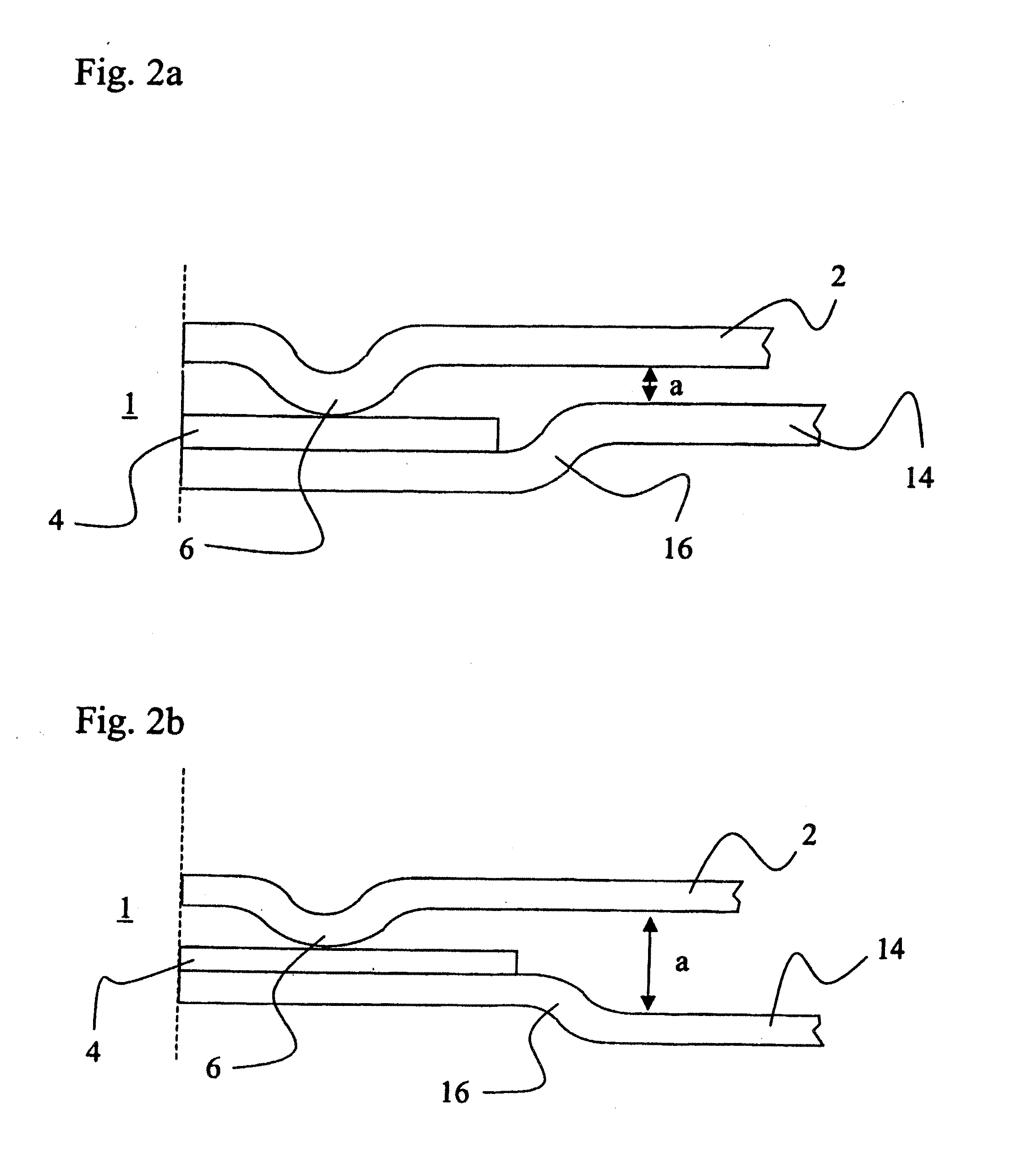
[0029]In the present invention an additional bead is provided in radial direction behind the combustion chamber. This bead, which can be implemented as a half bead or a full bead, accepts a portion of the pressure. Since the bead situated next to the combustion chamber must not accept the entire stress any longer, the bead tip and / or contact tip can be optimized in the pressure. Likewise, the second bead accepts an additional sealing function. These properties improve the sealing properties and have a positive influence on the lifetime of the cylinder head gasket.

Problems solved by technology

The area of such a gasket directly surrounding the combustion chamber is exposed to higher stresses during the operation of the engine.
If the bead positioned in direct force fit is not supported, and thus endures the entire stress, the lifetime of the gasket is thereby negatively influenced.
Thereby, the spring characteristic of the bead is influenced such that the bead becomes harder and also loses elasticity.
With the impact of pressure an uncoiling effect over the crest of the bead develops, which leads to high oscillation amplitudes in the vertical direction.

Method used


Image

  • Metal cylinder head gasket without a spacing layer
  • Metal cylinder head gasket without a spacing layer
  • Metal cylinder head gasket without a spacing layer

Examples


Embodiment Construction

[0033]On the left side of each figure one finds the area adjacent to the combustion chamber of the cylinder head gasket, while on the right side of each figure is the side oriented away from the combustion chamber.

[0034]The bead also rests upon the support ring and / or stopper. This principle is therefore designated as “bead on stopper”. In FIG. 1a a cylinder head gasket is shown, which comprises a functional layer 2 and a ring lining 4. The functional layer 2 comprises a full bead 6. The ring lining 4 comprises a full bead 8, in which rests the full bead 6, and a half bead 10 lying behind it as viewed in radial direction from the combustion chamber. In the area designated as A, in which the full bead 6 of the functional layer 2 rests upon the ring lining 4, occurs the greatest pressure in the built-in state. A portion of the pressure arising is absorbed by the half bead 10 of the ring lining 4 in the area designated as B, whereby the full bead 6 is relieved. Thereby, an additional s...


PUM


Abstract

One aspect of the invention relates to a cylinder head gasket provided with at least one opening corresponding to a combustion chamber of an internal combustion engine. The gasket has a function layer with a full bead and an annular support with a bead. The bead of the annular support is arranged on the side of the full bead which is oriented away from the combustion chamber. Another aspect of the invention relates to a cylinder head gasket having an upper functional layer, an annular support and a lower functional layer. The annular support is arranged between the upper and lower functional layers and is adjacent to the lower functional layer. The upper functional layer comprises one full bead, and the lower functional layer has a bead arranged on the side of the full bead which is oriented away from the combustion chamber.

Description

CROSS REFERENCE TO RELATED APPLICATIONS[0001]This application is a divisional application which claims priority to U.S. application Ser. No. 10 / 583,535, filed Jun. 3, 2009, PCT Application Serial No. PCT / EP2004 / 010628, filed Sep. 22, 2004, and German Patent Application No. 103 58 919.8, filed Dec. 16, 2003, all of which are incorporated herein by reference.BACKGROUND OF THE INVENTION[0002]1. Field of the Invention[0003]The present invention relates to a metallic cylinder head gasket without a spacing layer. In particular, it concerns a cylinder head gasket with only one functional layer.[0004]2. Related Art[0005]A cylinder head gasket ensures impermeability to gas between the cylinder block and cylinder head. Thereby, the cylinder head gasket must balance elastic vibrations between the cylinder head and cylinder block.[0006]The functional principle of metallic gaskets for cylinder head use in internal combustion engines is that an elastic sealing zone is present. The gasket is desig...

Claims


Application Information

Patent Timeline
IPC IPC(8): F02F11/00F16J15/08
CPCF16J15/0818F16J2015/0862F16J15/0825
Inventor SCHMITT, KLAUSFLEMMING, RALF
Owner FEDERAL MOGUL SEALING SYST
Learn More