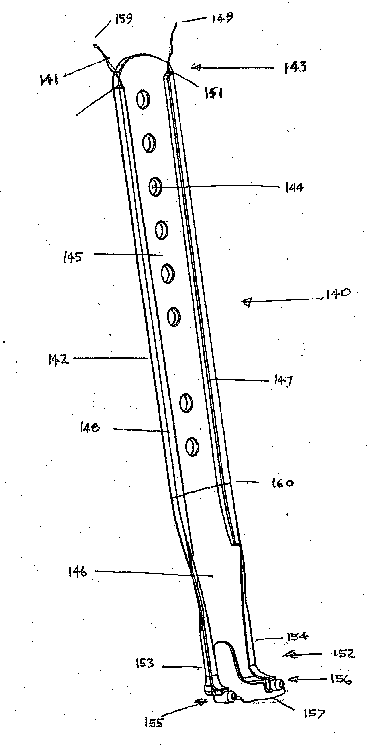
Amongst spinal surgeons it is recognized that the most difficult and dangerous part of the surgery on the anterior
lumbar disc spaces is
dissection, mobilization and maintenance of retraction of the vessels, and in particular the left common iliac
vein.
Some limited movement of the Hohmann blade is possible by bending.
Internally fixed retractors have limitations.
Insertion and removal can also be hazardous to vessels or other soft tissues.
The known externally fixed retractor blades have significant limitations.
When a patient's spine moves e.g. during impaction or positioning of implants, or other vigorous work, the lateral retractors tend to bounce and slip.
Contact with the bone by providing an additional point of stability helps reduce this, but it remains a problem.
If a
constant force is applied from the frame along the line of the blade, pushing the blade against the spine helps stability, but this can easily lead to the blade slipping or sliding posteriorly and causing tissue injury when the spine moves.
Inadvertent downward pressure by surgeons or their assistants on these blades also is a problem as it leads to posterior displacement, because there is usually little or no support for the blade from the bone relying as it dies essentially on friction grip.
One of the limitations of many existing retraction systems is the tendency for the vessels, in particular the left common iliac
vein, to bulge around the retractor, which can
expose the
vein to injury and impede the surgeon.
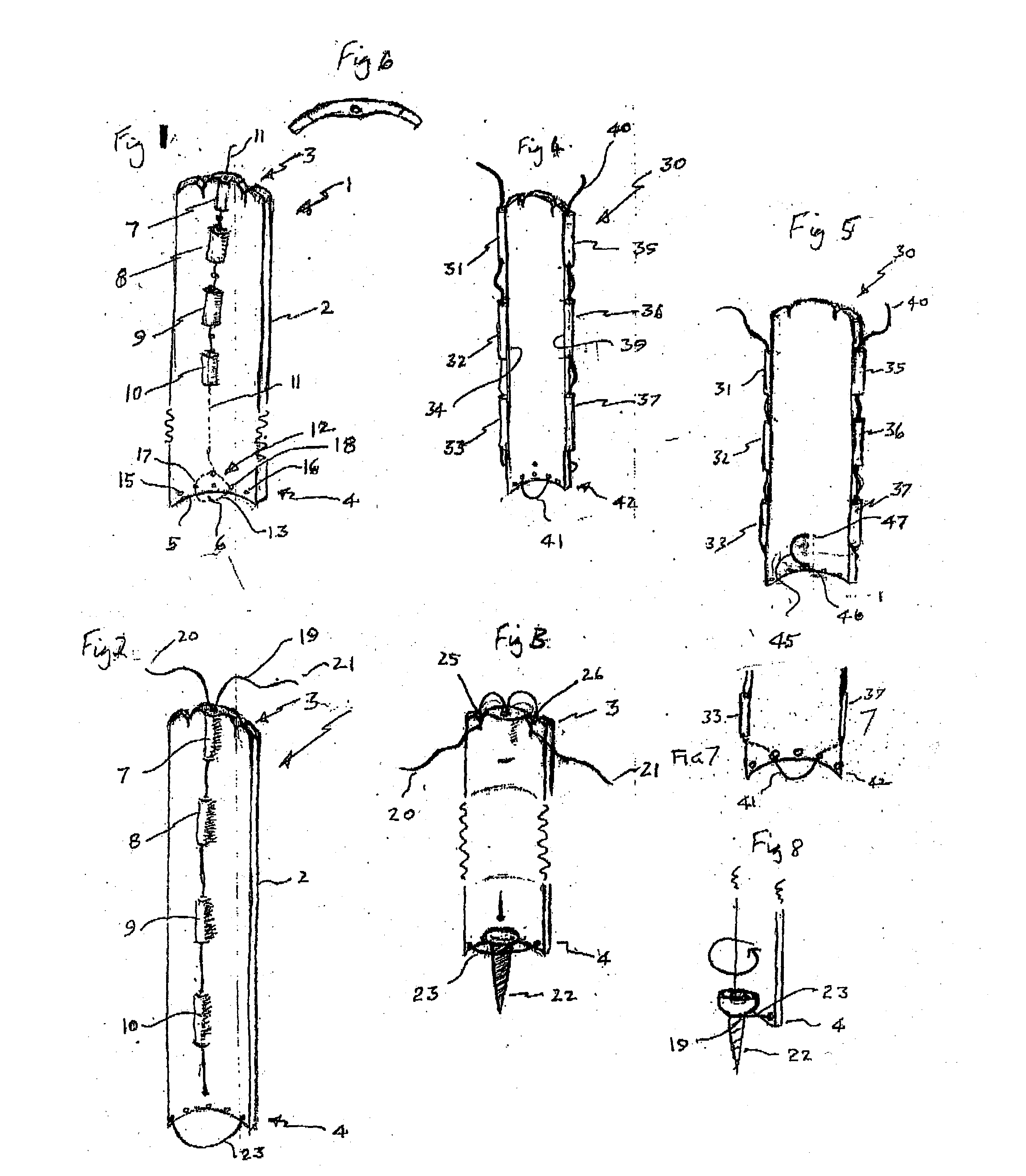
This provides good anchorage but there are dangers inherent in finding the optimal pin position and holding the blade in a position near the optimal pin anchorage position until the pin is passed through the blade.
There is a danger to
anatomical structures when the pin is moved around to find the optimal anchorage position as the pin could snag vital structures such as blood vessels.
There is another
disadvantage of the prior art assemblies in that the surgeon must hold the retractor blade perfectly still in the critical selected position while sliding a sharp potentially dangerous pin through the cannulation in the blade and into engagement with the spine.
Moving the retractor blade while the pin is on the bone incurs the risk of dragging the point of the pin over a difficult to see compressed vein which could be inadvertently impaled during pin
insertion.
An error of this kind can have fatal consequences.
There are some clinical limitations of the Serengeti retractor.
This is undesirable as the bone purchase may be reduced by a second
insertion.
Another limitation is that to remove the device, it requires to be fractured in two places to be removed easily, this requires use of a special tool.
During removal the retractor sometimes fractures on one side only, making removal,
time consuming and fiddly.
A third clinical limitation which occurs because they cannot be inserted after the screw and rod is that they cannot be used in revision cases prior to screw and rod removal.
These handheld retractors are bulky and have to be continuously held to maintain stability and prevent them falling out.
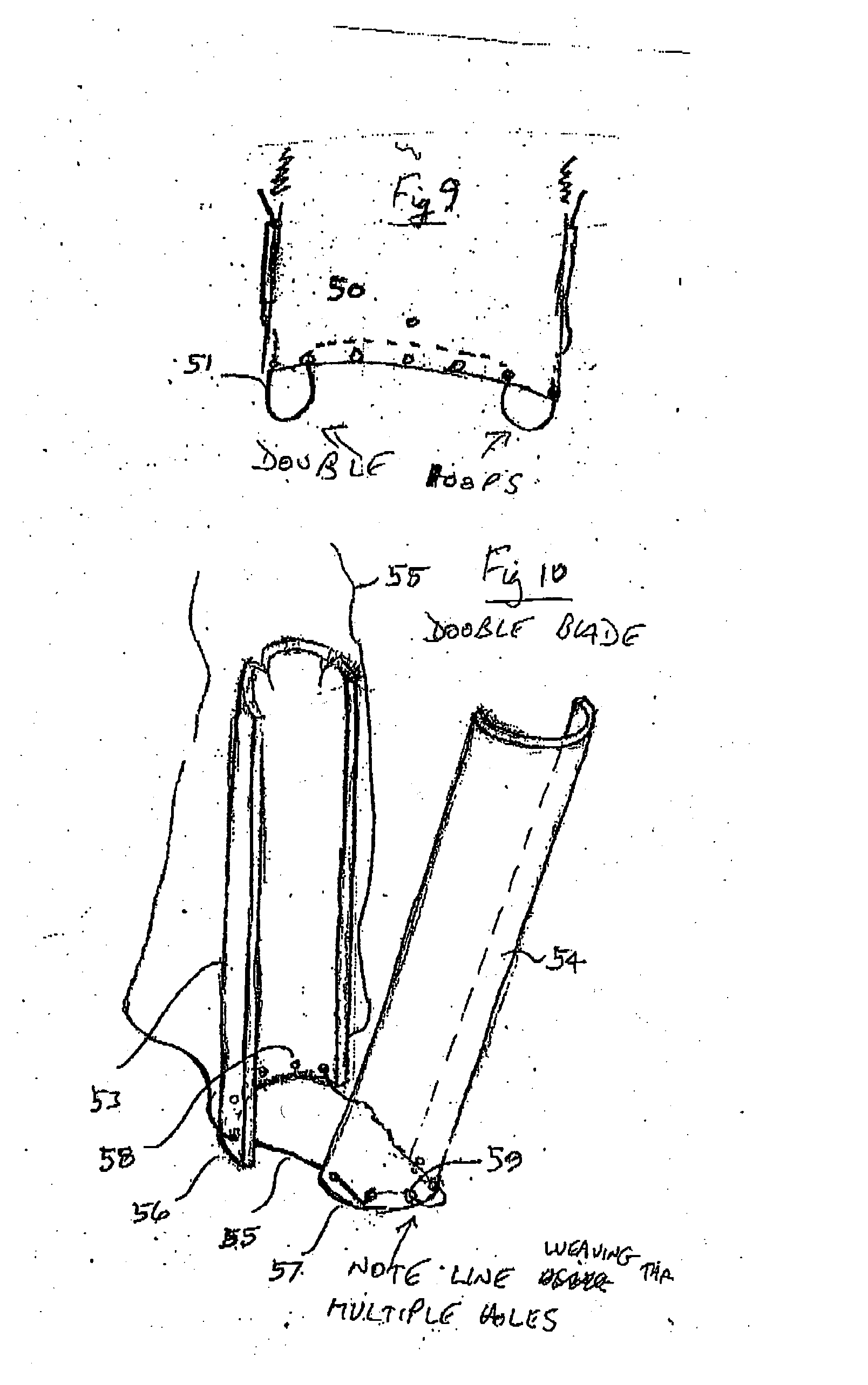
Use of a single channel or cannulation is less functional than the device described in the present application here because the shape and disposition of the distal loop is uncontrolled from a single opening.
Threading the distal loop line through a separate member to prevent line withdrawal accidentally would avoid this, but removal of the
assembly is less functional as the line cannot be
cut and pulled through without the separate member falling off in the wound.

