

Equipment for suspension of a car or counter weight in an elevator installation and methods for mounting and for maintenance of suspension means
Patent Information
- Authority / Receiving Office
- US · United States
- Patent Type
- Applications(United States)
- Current Assignee / Owner
- INVENTIO AG
- Publication Date
- 2006-08-10
- Estimated Expiration
- Not applicable · inactive patent
Smart Images
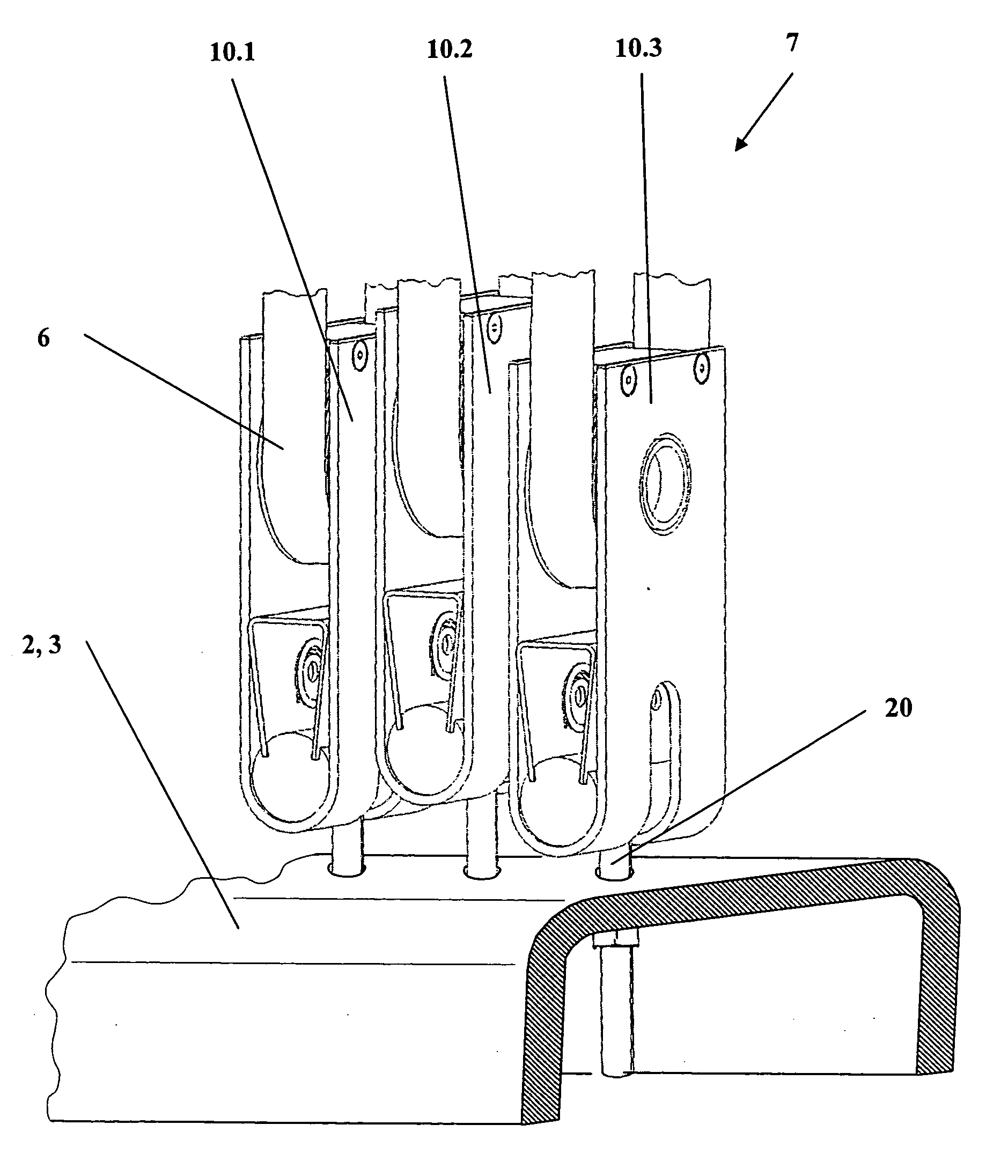
Figure 1 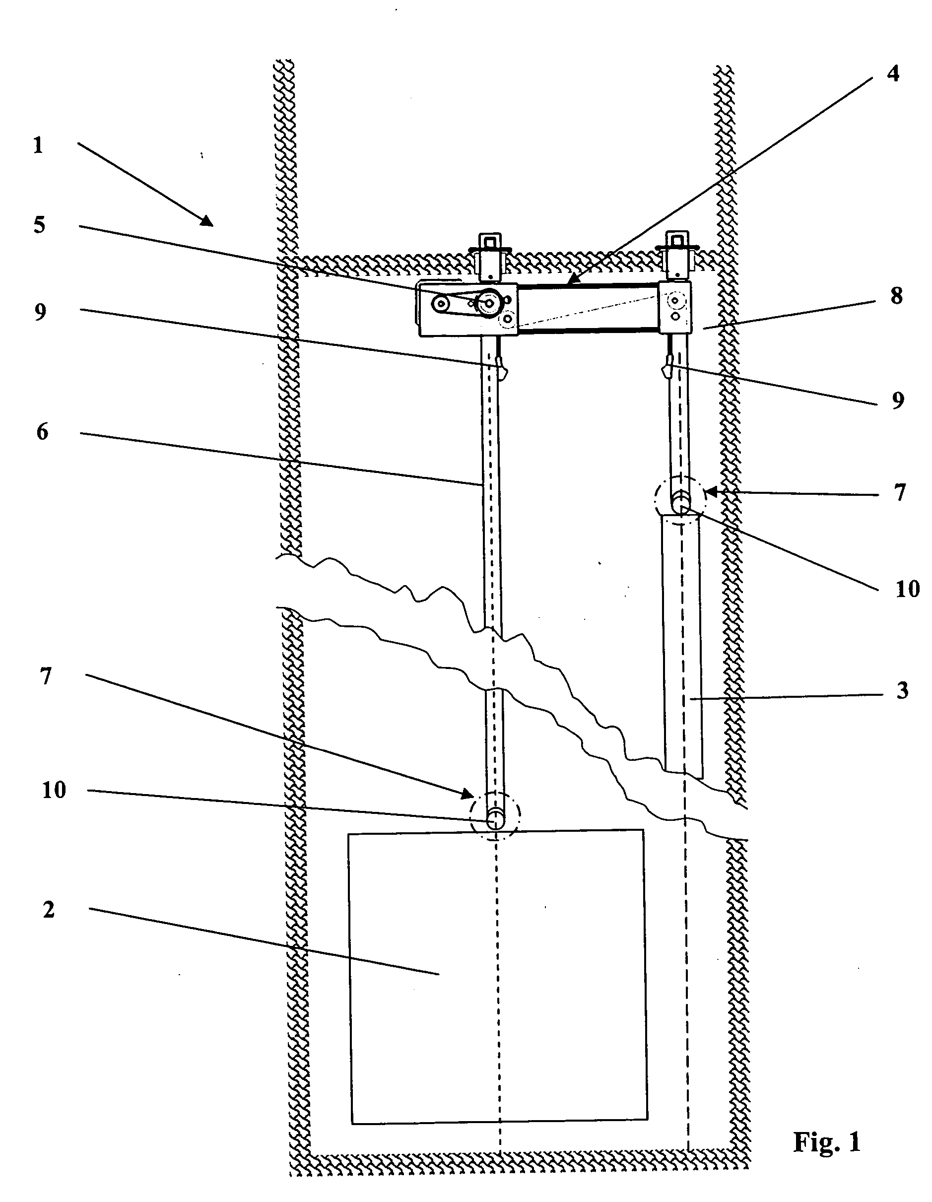
Figure 2 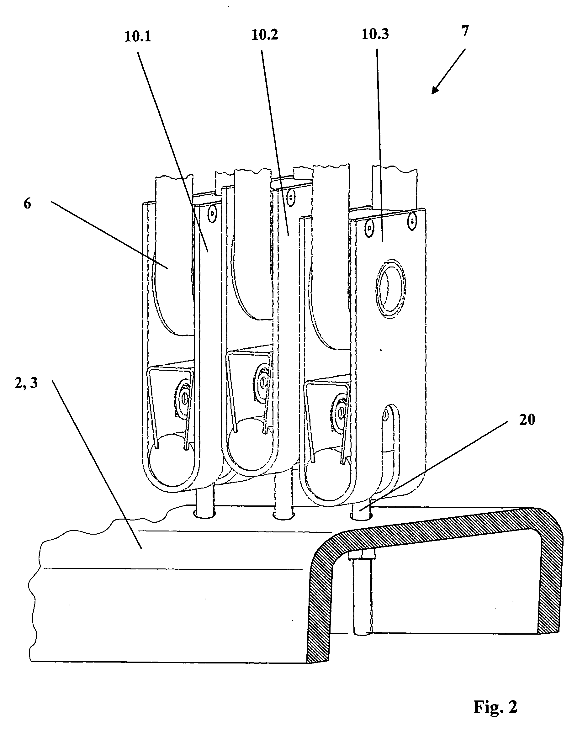
Figure 3
Abstract
Description
BACKGROUND OF THE INVENTION
[0001] The present invention relates to equipment for suspension of a car or a counterweight in an elevator installation and to methods for mounting and for maintenance of such suspension means.
[0002] German patent document DE 2333120 illustrates such an elevator installation, in which a car and a counterweight are suspended by means of looping around of steel belts. Several deflecting rollers are in that case combined into a deflecting roller unit, which is connected with the car or with the counterweight. The individual deflecting rollers are in that case arranged on a common axis so that the individual deflecting rollers are capable of different rotation.
[0003] However, this solution has disadvantages. The deflecting roller units have to be matched to the number of steel belts that are used and be correspondingly combined. Alignment of the deflecting roller unit to the take-off direction of the belts can take place only as a whole and an individual l...