Implantable hydrocephalus shunt system

a technology of hydrocephalus and shunt, which is applied in the direction of wound drain, intravenous device, other medical devices, etc., can solve the problems blockage easily caused, and over-drainage of similar harmful substances, so as to avoid damage to syringe and valve, avoid and/or minimize damage, reduce the effect of syringe and valve damag

Active Publication Date: 2012-09-13
CHRISTOPH MIETHKE
View PDF56 Cites 29 Cited by
  • Summary
  • Abstract
  • Description
  • Claims
  • Application Information

AI Technical Summary

Benefits of technology

[0075]According to the present application, damage to the syringe and valve are avoided and/or minimized when using a syringe to fill the valve.
[0076]On the actuation side, the membrane or the plunger is optionally provided with a funnel-shaped indentation. This guides the syringe needle away from the edge to the center. During the filling operation this prevents, restricts, and/or minimizes the needle from slipping towards the edge and being trapped ...

Problems solved by technology

The technical problem of the present application was to administer to the patient these medicaments/pharmaceuticals in liquid form or with the aid of liquids.
The blockage is easily caused by pieces of tissue or blood clots, which accu...

Method used


Image

  • Implantable hydrocephalus shunt system
  • Implantable hydrocephalus shunt system
  • Implantable hydrocephalus shunt system

Examples


Embodiment Construction

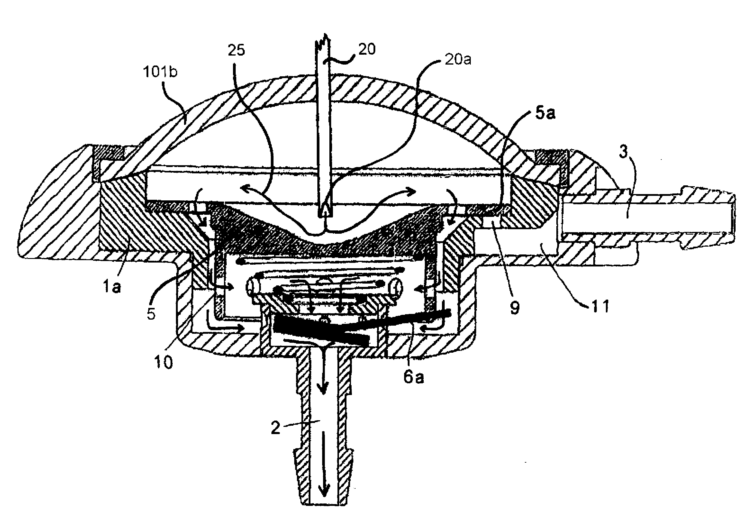
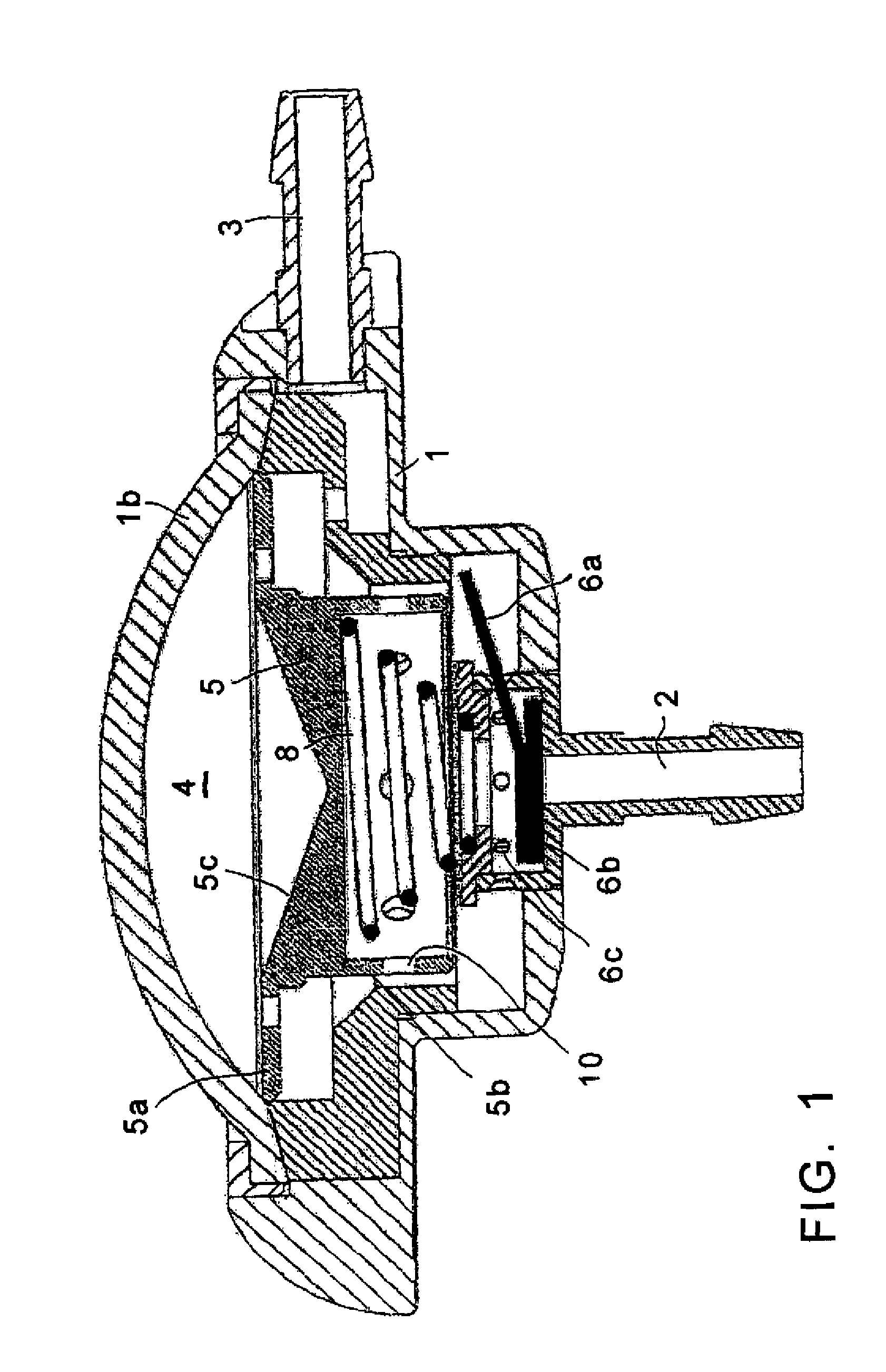
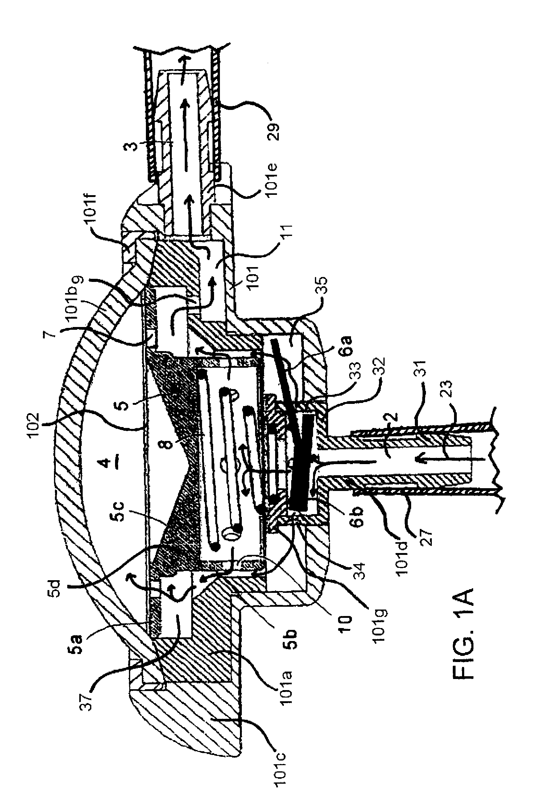
[0098]FIGS. 1 and 2 show the implanted hydrocephalus valve in various operational states. The valve is a component of a liquor drainage. Here an implanted drainage tube or passage leads from a ventricle catheter to the valve and a further implanted drainage tube or passage from the valve in the stomach of the patient.

[0099]The valve comprises a housing 1 with an inlet 2, an outlet 3, an interior and cavity 4. A valve cap 6b that seals the inlet 3 with a lever 6a is provided in the interior of the valve. The valve cap 6b is let in the housing such that the valve cap in the embodiment does not need and / or desire a hinged connection with the housing. The valve cap 6b corresponds to a lid that however, because of the guiding in the housing and because of the collaboration of lever 6a with the plunger 5, behaves as a valve cap and is therefore designated here as a valve cap.

[0100]In other embodiments, another guiding or a hinged connection with the housing is provided instead of the guid...


PUM


Abstract

An implantable hydrocephalus shunt system. The abstract of the disclosure is submitted herewith as required by 37 C.F.R. §1.72(b). As stated in 37 C.F.R. §1.72(b): A brief abstract of the technical disclosure in the specification must commence on a separate sheet, preferably following the claims, under the heading “Abstract of the Disclosure.” The purpose of the abstract is to enable the Patent and Trademark Office and the public generally to determine quickly from a cursory inspection the nature and gist of the technical disclosure. The abstract shall not be used for interpreting the scope of the claims. Therefore, any statements made relating to the abstract are not intended to limit the claims in any manner and should not be interpreted as limiting the claims in any manner.

Description

[0001]This application is a Continuation-In-Part application of International Patent Application No. PCT / EP2010 / 007817, filed on Dec. 21, 2010, which claims priority from Federal Republic of Germany Patent Application No. 10 2009 060 533.9, filed on Dec. 23, 2009. International Patent Application No. PCT / EP2010 / 007817 was pending as of the filing date of this application. The United States was an elected state in International Patent Application No. PCT / EP2010 / 007817.BACKGROUND[0002]1. Technical Field[0003]The present application relates to a subcutaneously implantable hydrocephalus shunt system.[0004]2. Background Information[0005]Background information is for informational purposes only and does not necessarily admit that subsequently mentioned information and publications are prior art.[0006]In medicine, a connection between normally separated vessels or cavities is called a shunt. Various synthetic shunts are known. Malformations that occur in nature and likewise make a connecti...

Claims


Application Information

Patent Timeline
IPC IPC(8): A61M1/00
CPCA61M1/3655A61M5/14276A61M27/006A61M2039/2473A61M39/24A61M2039/242A61M39/0208
Inventor MIETHKE, CHRISTOPH
Owner CHRISTOPH MIETHKE
Why Eureka
Try Eureka