Operation machine

applied in the field of working machine, can solve the problems of no proposal, no study has been made on such a technology of working machine and ground surface contact change, and achieve the effect of improving the efficiency of the operation

Active Publication Date: 2012-09-13
NIHON KENKI CO LTD
View PDF5 Cites 43 Cited by
  • Summary
  • Abstract
  • Description
  • Claims
  • Application Information

AI Technical Summary

Benefits of technology

[0022]The present invention is provided with the above-described features, and therefore, can compute moment by moment the dynamic stability of the working machine and the state of contact of the working machine with the ground while taking into consideration an inertia force or external force applied to the working machine, and can display them without delay.

Problems solved by technology

With the conventional technologies, however, no proposal has been made yet as to a determination means that enables to calculate and determine the stability of a working machine moment by moment while taking an inertia force into consideration.
Moreover, no study has been made yet on such an operation that the points of contact of a working machine with the ground surface changes, for example, when a blade is in contact with the ground or the working machine is in a jacked-up state.

Method used


Image

  • Operation machine
  • Operation machine
  • Operation machine

Examples


first embodiment

[0040]A description will hereinafter be made about the first embodiment of the present invention.

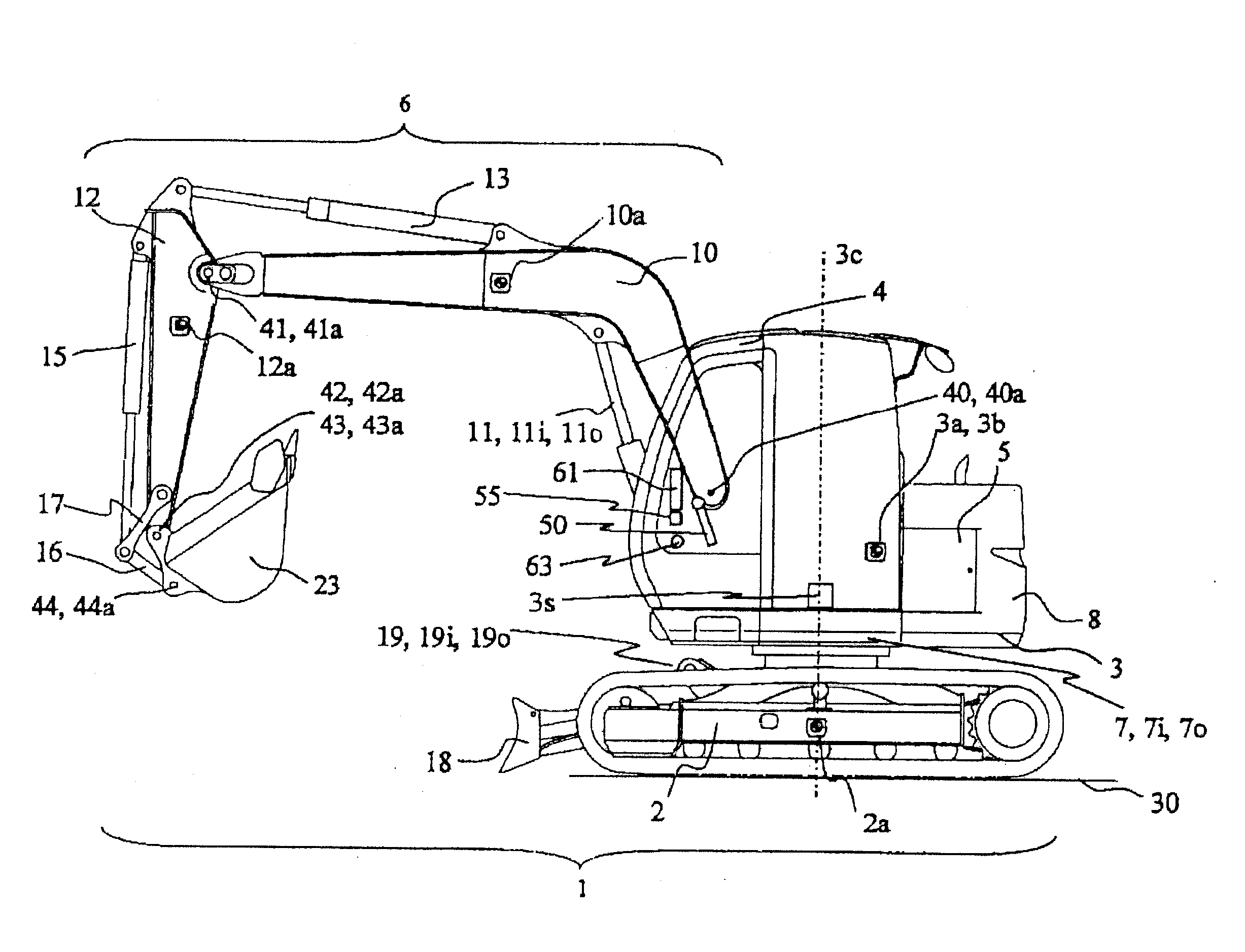
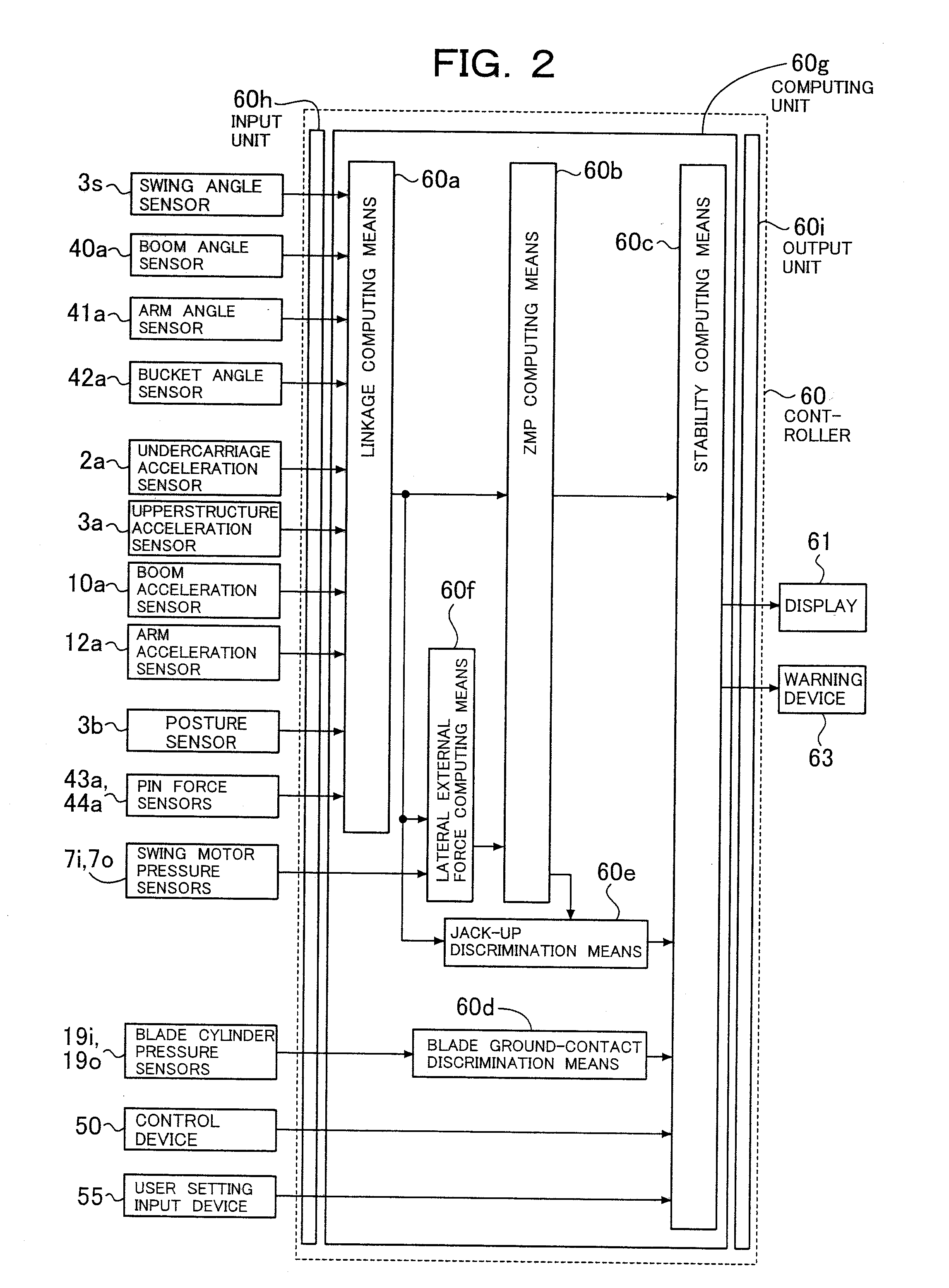
[0041]FIG. 1 is a schematic side view showing a working machine according to the first embodiment. In the working machine 1 according to the first embodiment, an upperstructure 3 is rotatably mounted on an undercarriage 2, and the upperstructure 3 is rotatably driven by a swing motor 7. On the upperstructure 3, an operator's cab 4 and an engine 5 are mounted. On a rear part of the upperstructure 3, a counterweight 8 is mounted. In addition, a controller 60 that controls the entire working machine 1 is arranged to make up the working machine 1.

[0042]On the upperstructure 3, a boom 10 is arranged pivotally up and down via a fulcrum 40 as a joint, and on a free end of the boom 10, an arm 12 is pivotally arranged via a fulcrum 41 as a joint. Further, on a free end of the arm 12, a bucket 23 is pivotally arranged as a working attachment via a fulcrum 42 as a joint. It is to be noted that the ...

second embodiment

[0167]The second embodiment of the present invention will next be described with reference to FIG. 10 and FIG. 11. FIG. 10 is a schematic side view showing a working machine according to the second embodiment, and FIG. 11 is a top plan view showing an upperstructure in the second embodiment by modeling it. In FIG. 10 and FIG. 11, similar elements of structure as the corresponding ones in the first embodiment are identified by like signs, and their description is omitted.

[0168]The second embodiment is different from the first embodiment in that a swing mechanism, which performs a horizontal swing, is arranged between an upperstructure 3 and a boom 10. A description will hereinafter be made primarily about this difference from the first embodiment.

[0169]

[0170]As shown in FIG. 10, in the working machine 1a according to the second embodiment, the upperstructure 3 is rotatably mounted on an undercarriage 2, and the upperstructure 3 is driven by a swing motor 7. On the upperstructure 3, a...

third embodiment

[0183]The third embodiment of the present invention will be described with reference to FIG. 13 and FIG. 14. FIG. 13 is a schematic side view showing a working machine according to the third embodiment, and FIG. 14 is a top plan view showing an upperstructure in the third embodiment by modeling it. In FIG. 13 and FIG. 14, similar elements of structure as the corresponding ones in the first embodiment are identified by like signs, and their description is omitted.

[0184]The third embodiment is different from the first embodiment in that it has, as a horizontal pivot mechanism, an offset mechanism which allows the front working mechanism 6 to undergo a horizontal translation at its front part beyond an arm 12. A description will hereinafter be made primarily about this difference from the first embodiment.

[0185]As shown in FIG. 13, the working machine 1b according to the third embodiment is primarily constructed of an undercarriage 2, an upperstructure 3, and a swing motor 7 for drivin...


PUM


Abstract

Disclosed is a working machine that computes and displays moment by moment its dynamic stability and its state of contact with a ground in view of an inertia force and an external force applied to the working machine. Specifically, a working machine is provided with an undercarriage, a working machine main body mounted on the undercarriage, a front working mechanism attached pivotally in an up-and-down direction to the working machine main body, and a working attachment connected to a free end of the front working mechanism. The working machine includes a ZMP computing means for calculating coordinates of a ZMP by using position information, acceleration information and external force information on respective movable portions of the main body, which includes the front working mechanism, and undercarriage, and a stability computing means for calculating a support polygon formed by plural ground points of the working machine with a ground, and, when the ZMP is included in a warning region formed inside a perimeter of the support polygon, producing a tipping warning sound. The ZMP and the support polygon, which includes the warning region, is computed, and a display or warning is produced.

Description

TECHNICAL FIELD[0001]This invention relates to a working machine, and specifically to a working machine useful in construction work, demolition work, civil engineering work and / or the like.BACKGROUND ART[0002]Known as construction machines employed in construction work, demolition work, civil engineering work and / or the like include those having an upperstructure mounted rotatably on an undercarriage and a multi-articulated front working mechanism attached pivotally up and down to the upperstructure. As one example of such working machines, there is a demolition work machine constructed by using a hydraulic excavator as a base.[0003]Such a working machine includes a front working mechanism, which is composed of a boom and arm and is connected pivotally up and down to an upperstructure via a joint, and a grapple, bucket, breaker, crusher or the like attached to a free end of the arm via a joint, so that it can perform work such as demolition work of structural objects or dismantling ...

Claims


Application Information

Patent Timeline
Patent Type & Authority Applications(United States)
IPC IPC(8): G06F19/00
CPCB66C23/905E02F9/264E02F9/24
Inventor MIZUOCHI, MARIKOISHII, AKINORIYAMAGUCHI, JINICHI
Owner NIHON KENKI CO LTD
Why Eureka
Try Eureka