Method of driving electro-optical device and electronic apparatus
a technology of electrooptical devices and electronic devices, applied in the direction of static indicating devices, identification means, instruments, etc., can solve problems such as delay in displaying images, and achieve the effect of reducing the time for writing data and reducing the manufacturing cost of a display devi
- Summary
- Abstract
- Description
- Claims
- Application Information
AI Technical Summary
Benefits of technology
Problems solved by technology
Method used
Image
Examples
first embodiment
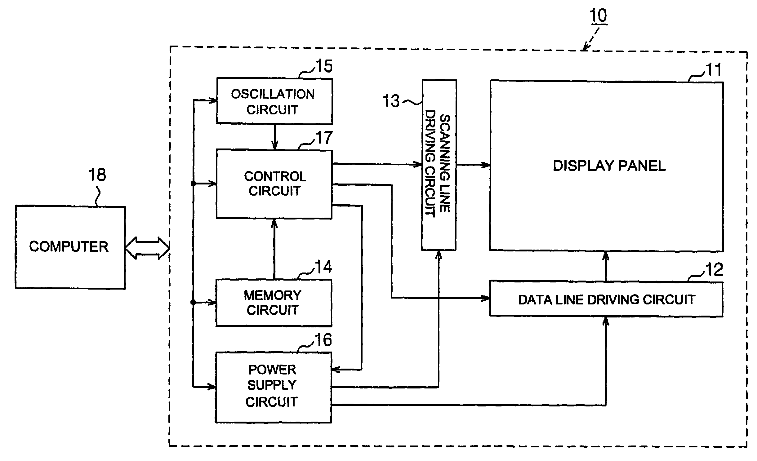
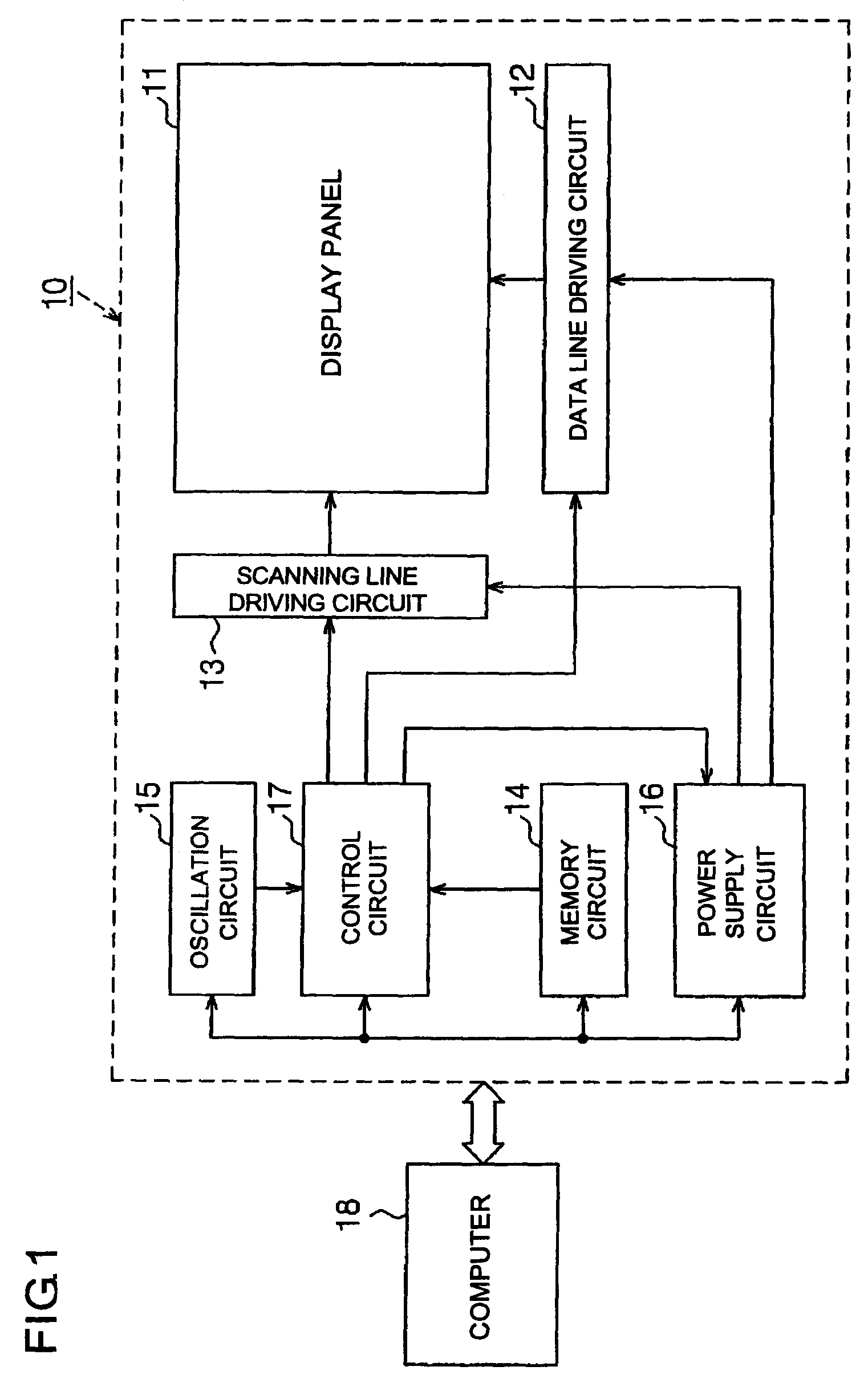
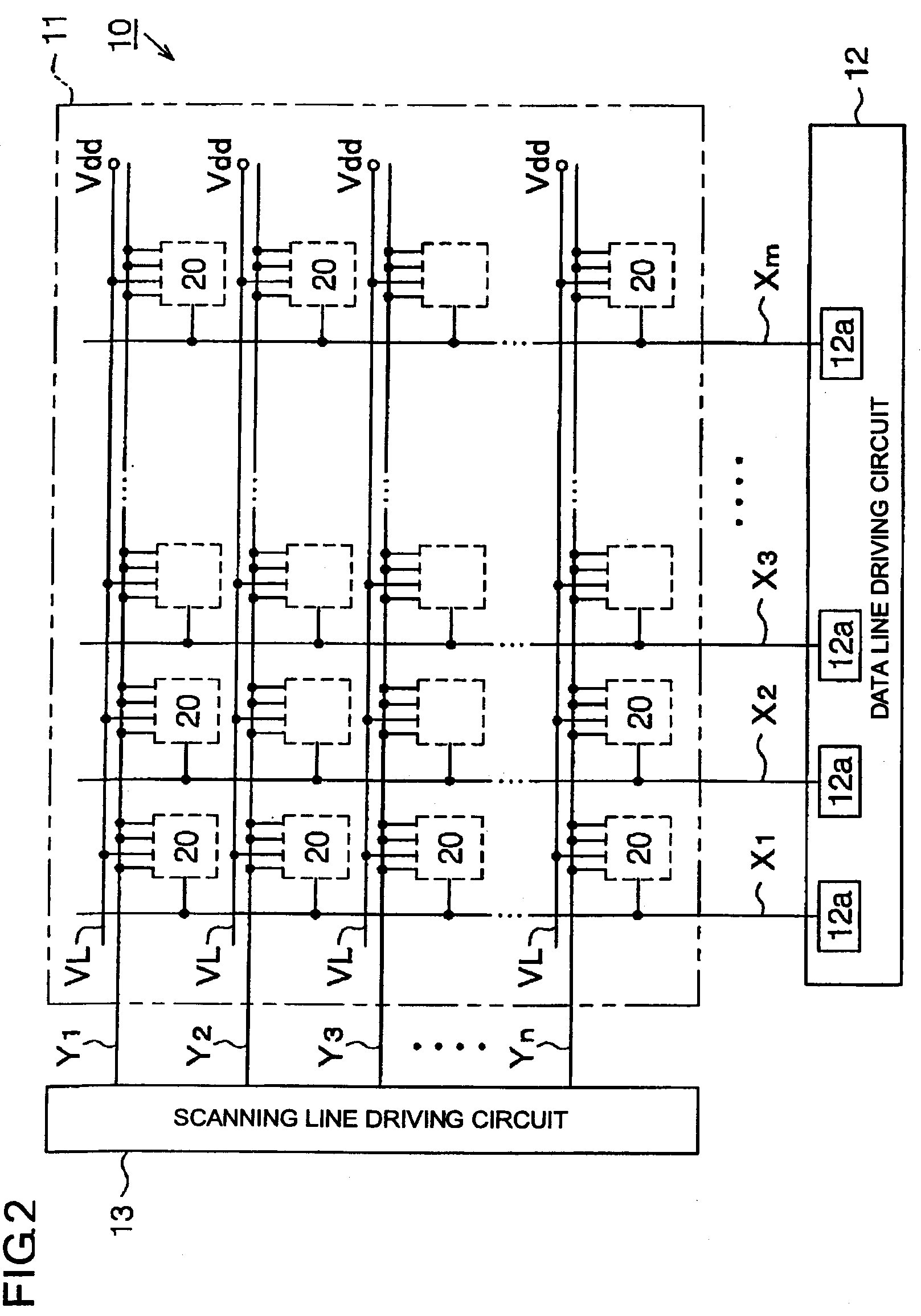
[0038]the present invention will be described with reference to FIGS. 1 to 4. FIG. 1 is an exemplary block circuit diagram illustrating the electrical structure of an organic EL display 10. FIG. 2 is an exemplary block circuit diagram illustrating the electrical structure of a display panel, a data line driving circuit, and a scanning line driving circuit.
[0039]In FIG. 1, the organic EL display 10 can include a display panel 11, a data line driving circuit 12, a scanning line driving circuit 13, a memory circuit 14, an oscillation circuit 15, a power supply circuit 16, and a control circuit 17. The respective elements 11 to 17 of the organic EL display 10 may be formed of independent electronic parts. For example, each of the elements 11 to 17 may be formed of a one-chip semiconductor integrated circuit device. Further, all or some of the elements 11 to 17 may be formed of an integrated electronic part. For example, the data line driving circuit 12 and the scanning line driving circ...
second embodiment
[0082] the drain of the driving transistor Qd is connected to the anode of the organic EL element 21. The cathode of the organic EL element 21 is grounded. The source of the driving transistor Qd is connected to the power line VL. The gate of the driving transistor Qd is electrically connected to the coupling capacitor Cp, the storage capacitor Co, and the controlling transistor Qct.
[0083]Specifically, the gate of the driving transistor Qd is connected to the first electrode La of the coupling capacitor Cp. The second electrode Lb of the coupling capacitor Cp is connected to the drain of the switching transistor Qsw. The gate of the switching transistor Qsw is connected to the first sub-scanning line Y11 that constitutes the first scanning line Y1.
[0084]The gate of the driving transistor Qd is connected to the third electrode Lc of the storage capacitor Co. The fourth electrode Ld of the storage capacitor Co is connected to the power line VL. The gate of the driving transistor Qd is...
PUM
 Abstract
Description
Claims
Application Information
 - R&D
- Intellectual Property
- Life Sciences
- Materials
- Tech Scout
- Unparalleled Data Quality
- Higher Quality Content
- 60% Fewer Hallucinations
Browse by: Latest US Patents, China's latest patents, Technical Efficacy Thesaurus, Application Domain, Technology Topic, Popular Technical Reports.
© 2025 PatSnap. All rights reserved.Legal|Privacy policy|Modern Slavery Act Transparency Statement|Sitemap|About US| Contact US: help@patsnap.com


