System Design Combining Functional Decomposition And Object-Oriented Programming

a functional decomposition and system design technology, applied in the field of system design combining functional decomposition and object-oriented programming, can solve the problems of not being well adapted to a hierarchical structure, unable to easily manage the breakup of the system into an appropriate hierarchy, and unable to effectively develop larger and more complex products and systems. , to achieve the effect of reducing the amount of complexity in the system and facilitating the understanding of the system operation

Inactive Publication Date: 2012-09-13
BAE SYST INFORMATION & ELECTRONICS SYST INTERGRATION INC
View PDF2 Cites 0 Cited by
  • Summary
  • Abstract
  • Description
  • Claims
  • Application Information

AI Technical Summary

Benefits of technology

[0040]The important characteristic concerning objects is that objects provide a better form of communication between systems engineers and the other-disciplined engineers.
[0048]One advantage of using objects is called “encapsulation,” which allows one to take functions and organize them into a specific object. Thus, anytime that one needs a function, one can know how to communicate with that object to get the function performed. Encapsulation allows one to group functions by object and optimize the amount of communication. It will be appreciated that the less the communication between the objects, the more efficient is the system. Thus, use of objects allows one to optimize the particular architecture.
[0051]The result of this multi-level hierarchical functional decomposition with object-oriented techniques at each level permits one to understand the entire system through small sections or segments so that one can understand a portion of the design and get a handle on it.
[0052]It has been said that a typical person can keep track of 7 to 9 things at any given time. Thus, to minimize the amount of complexity in a system, one provides object-oriented techniques that operate at a given level in which the objects permit the engineer to keep track of a reasonable number of things; and then provide the ability to communicate between various levels.
[0053]Specifically and as an example, one might have nine levels in a functional object decomposition. At any given level one might have 3 to 100 objects. This, however, may be somewhat complex. But if one needs to understand the system from an overall view, one can examine a particular level and look at the system functions of the objects in this level. Thus, for instance, there may be nine or ten objects in a level and one can understand the operation of the system more easily by breaking or decomposing the system into levels containing objects.
[0054]Another feature of the subject invention is that one can get a handle on the entire system by looking down a level and looking at the object-oriented designs that go on within that level so that one can get a detailed understanding of what is going on at that level.

Problems solved by technology

Currently there are challenges associated with efficiently and effectively developing larger and more complex products and systems for a wide variety of applications.
However, the available methods and tools only loosely imply a development approach instead of actually defining one.
The problem in such a functional decomposition strategy is that if one has 4,000-5,000 tasks to do, one cannot easily manage the breakup of the system into an appropriate hierarchy.
If one wanted to use object-oriented techniques for complex system design, they would not be well adapted to a hierarchical structure since the object-oriented techniques all have the objects at the same level.
Thus, object-oriented techniques were not generally utilized in complex system architecture or design.
The problem with such an approach is poor communication between the systems engineers and the electrical engineers, mechanical engineers and software engineers.
The result of a lack of communication or the lack of each engineer knowing where his task lies within the hierarchy can result in glaring omissions.
For instance, in designing a firefighting system in which one looks for forest fires and seeks to put them out, if one forgets to take into account that dropping water on an individual may cause injury or death and that the location of the individual must be accurately known when, for instance, a tanker drops flame retardant over a given area, then the omission is critical.

Method used


Image

  • System Design Combining Functional Decomposition And Object-Oriented Programming
  • System Design Combining Functional Decomposition And Object-Oriented Programming
  • System Design Combining Functional Decomposition And Object-Oriented Programming

Examples


Embodiment Construction

[0077]In terms of notation to support the implementation of the functional object-oriented design framework, the Unified Modeling Language (UML) and its system-based variant SYSML are used due to UML's status as the de-facto standard for object-oriented development. In one embodiment, the subject functional object design methodology relies heavily on UML with some extensions that are specific to the specific development tool being used. Even though some of the notations used are closely aligned with the selected development tool, in nearly all cases there are alternate representations that can be achieved using purely UML or SYSML constructs.

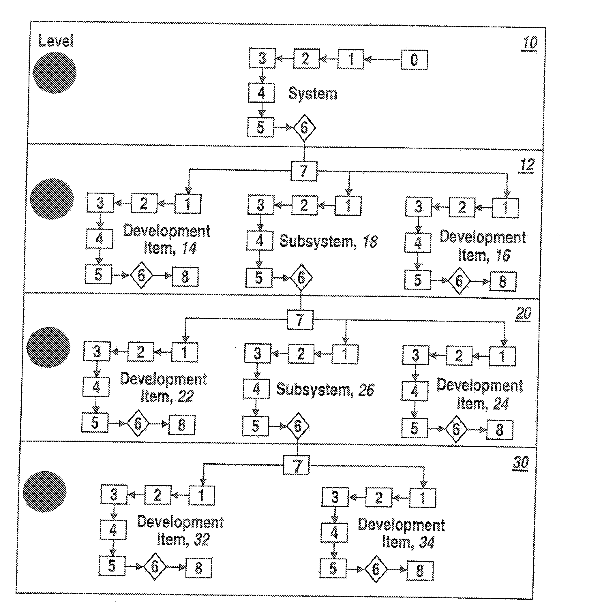
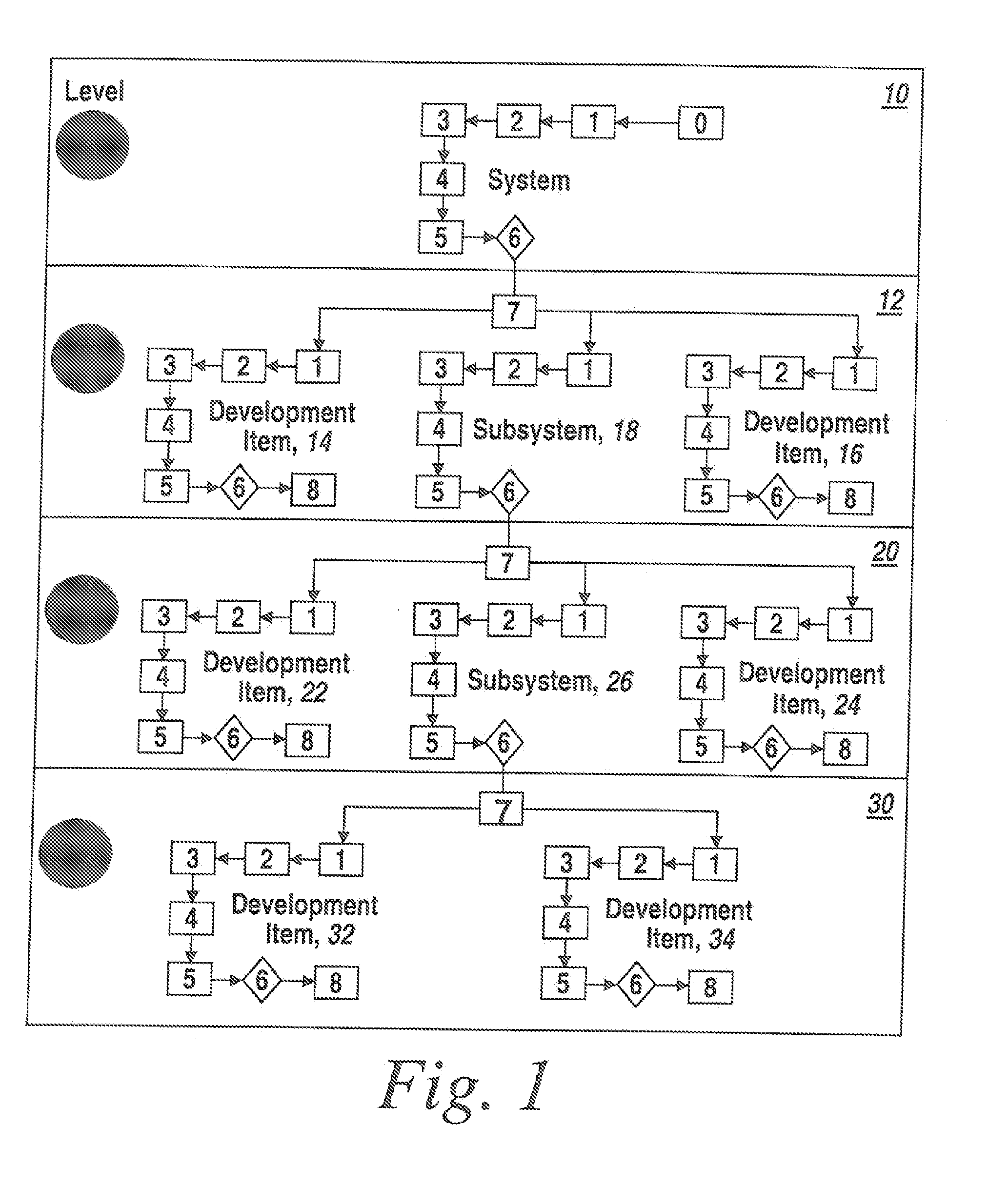
[0078]Referring now to FIG. 1, this figure depicts the development of a hypothetical system by iteratively using the functional object design steps documented above.

[0079]In FIG. 1, Level 0, shown at 10, is the “System” or top-level of the development. As the FOD steps are performed at this level, the objects at the next level 12, in this case L...


PUM


Abstract

An architecture for designing complex systems includes combining functional decomposition and object-oriented techniques at each level along with specifying links between the levels as well as links between the objects at a level to promote understanding of the system under development and assist both the system design engineers and the hardware and software engineers to develop the system.

Description

RELATED APPLICATIONS[0001]This Application is a divisional of U.S. Ser. No. 11 / 657,952 filed Jan. 25, 2007 and claims rights under 35 USC §119(e) from U.S. Provisional Application Ser. No. 60 / 789,210 filed Apr. 3, 2006, the contents of which are incorporated herein by reference.STATEMENT OF GOVERNMENT INTEREST[0002]This invention was made with United States Government support under Contract No. M4422 with the Joint Strike Fighter Program. The United States Government has certain rights in this invention.FIELD OF THE INVENTION[0003]This invention relates to a method of generating a specification for a complex project and more particularly to the use of combined object-oriented programming and functional decomposition techniques to provide a consistent design methodology for architecting complex systems.BACKGROUND OF THE INVENTION[0004]Currently there are challenges associated with efficiently and effectively developing larger and more complex products and systems for a wide variety o...

Claims


Application Information

Patent Timeline
Patent Type & Authority Applications(United States)
IPC IPC(8): G06F9/44
CPCG06F8/10
Inventor SAWYER, GEORGE A.CARRARA, DON L.
Owner BAE SYST INFORMATION & ELECTRONICS SYST INTERGRATION INC
Why Eureka
Try Eureka