Recirculating product injection nozzle

a technology of product injection and nozzle, which is applied in the direction of machines/engines, mechanical equipment, lighting and heating apparatus, etc., can solve the problems of affecting the combustion process, and affecting the combustion process, and achieves the effect of sufficient swirl strength

Active Publication Date: 2012-09-20
COLLINS ENGINE NOZZLES INC
View PDF10 Cites 60 Cited by
  • Summary
  • Abstract
  • Description
  • Claims
  • Application Information

AI Technical Summary

Benefits of technology

[0014]The invention also provides a recirculation product injection nozzle having an outer air swirler ring mounted to a nozzle housing. The outer air swirler ring includes a radial swirler configured to impart swirl to a flow of compressor discharge air from upstream of the inlet end with sufficient swirl strength to recirculate combustion products from downstream of the outlet end into an outer recirculation zone in proximity with the outlet end of the nozzle housing. An outer fuel injector ring is mounted in an insulation cavity of the outer air swirler ring downstream of the radial swirler and is configured and adapted to inject a spray of fuel into the outer recirculation zone downstream of the outlet end. The outer fuel injector ring can inject a small percentage of air to assist atomization and vaporization.

Problems solved by technology

However, operating at leaner, higher pressure conditions leads to increased probability and magnitude of combustion instabilities that can result in flame blow out or induce vibration modes that can damage engine components.
These methods are susceptible to lean instabilities that limit engine operating envelopes.
This leads to instabilities at higher frequencies, which are more damaging than low frequency instabilities as they can couple with resonating acoustic patterns.
This approach can also increase levels of unburned hydrocarbons (UHC) and / or carbon monoxide (CO) which are also environmentally damaging.
This in turn trips an unstable fluid dynamic structure, which leads to fluctuations in heat release rate, and so on.
The inability of coupling of this kind to occur in distributed combustion inhibits strong acoustic waves that could otherwise damage the combustor or turbine blades.
These ducts and / or heat exchangers in conventional burners are heavy and take up considerable space and have therefore limited the practical application of distributed combustion.

Method used


Image

  • Recirculating product injection nozzle
  • Recirculating product injection nozzle
  • Recirculating product injection nozzle

Examples


Embodiment Construction

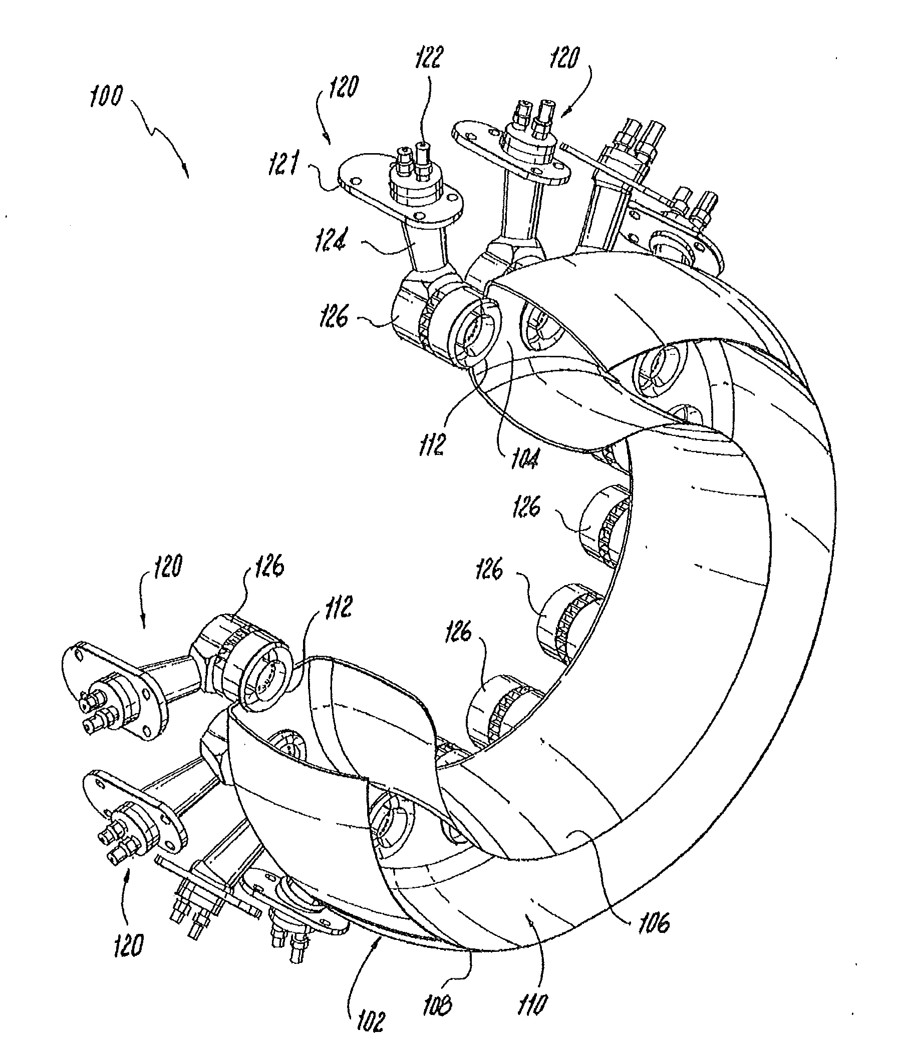
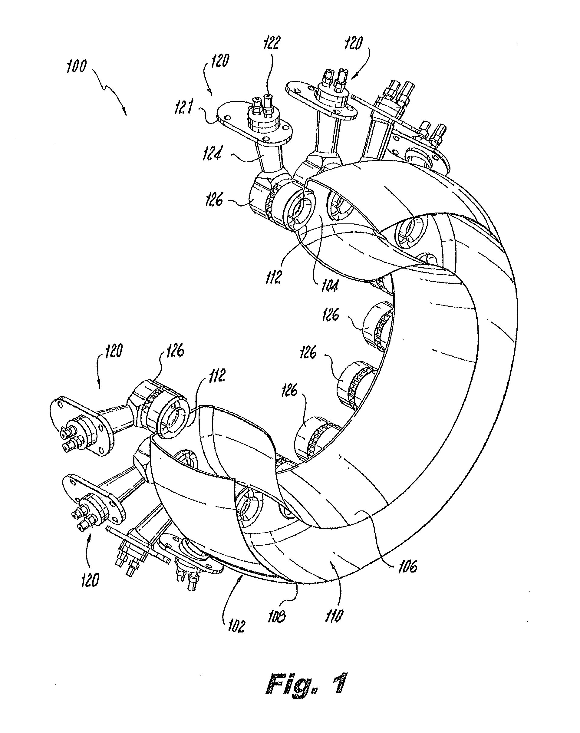
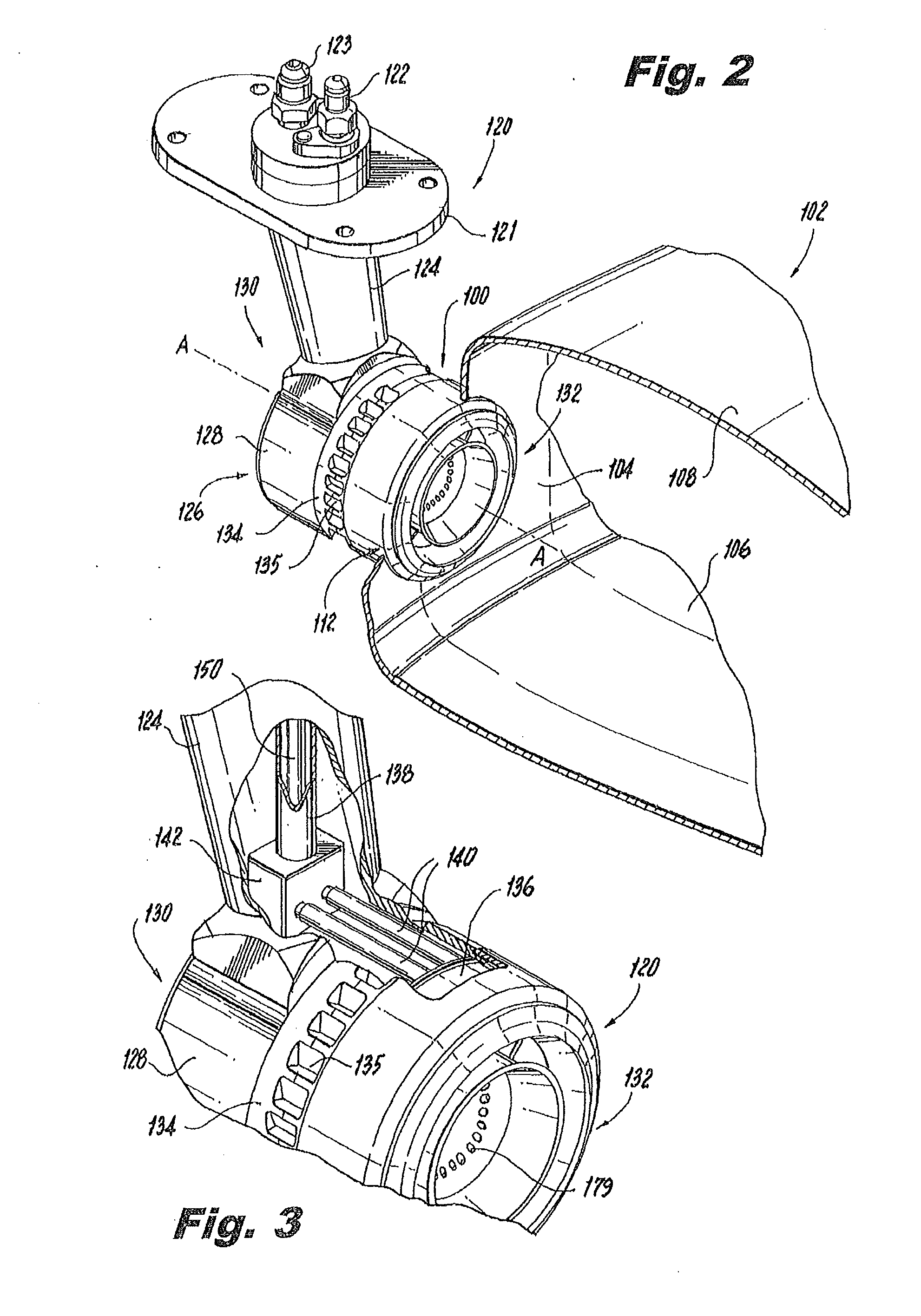
[0035]Reference will now be made to the drawings wherein like reference numerals identify similar structural features or aspects of the subject invention. For purposes of explanation and illustration, and not limitation, a partial view of an exemplary embodiment of a combustion system in accordance with the invention is shown in FIG. 1 and is designated generally by reference character 100. Other embodiments of combustion systems in accordance with the invention, or aspects thereof, are provided in FIGS. 2-12, as will be described. The systems of the invention can be used to inject and combust fuel and air in a distributed manner using recirculated combustion products to improve emissions and lean burn stability for gas turbine engines and the like.

[0036]Aero gas turbine engines have progressively been designed to operate at leaner fuel-to-air ratios in order to reduce emissions of NOX, and at higher pressure to increase efficiency. The trend toward higher pressure, lean combustion ...


PUM


Abstract

Combustion systems and the related methods operate to supply a stream of combustion products to a turbine in a gas turbine engine by forming an outer recirculation zone of recirculating combustion products within a combustor and by forming an inner recirculation zone inboard of the outer recirculation zone. The inner and outer recirculation zones are formed by imparting swirl to compressor discharge air passing through an outer air swirler and an inner air swirler radially inboard of the outer air swirler. Fuel is injected from an outer fuel injector into the outer recirculation zone, and fuel is also injected from an inner fuel injector into the inner recirculation zone.

Description

CROSS-REFERENCE TO RELATED APPLICATIONS[0001]This application claims priority to U.S. Provisional Patent Application No. 61 / 454,356 filed Mar. 18, 2011, which is incorporated by reference herein in its entirety.BACKGROUND OF THE INVENTION[0002]1. Field of the Invention[0003]The present invention relates to combustion systems, and more particularly to lean combustion systems for distributed combustion, such as in gas turbine engines.[0004]2. Description of Related Art[0005]A number of nozzles and injectors are known in the art for injecting fuel for combustion, such as in furnaces, gas turbine engines, and the like. The trend in the gas turbine industry, for example, has been to operate engines at increasingly lean fuel-to-air ratios and under higher combustor pressures to reduce emissions of environmentally harmful products of incomplete combustion, such as oxides of nitrogen (NOX) and to reduce specific fuel consumption. However, operating at leaner, higher pressure conditions lead...

Claims


Application Information

Patent Timeline
Patent Type & Authority Applications(United States)
IPC IPC(8): F02C7/22
CPCY02E20/342F23C2900/99001F23R3/343F23R3/283F23C9/006F23R3/12F23R2900/03282F23R3/50Y02T50/675F23R3/16Y02E20/34Y02T50/60
Inventor OVERMAN, NICHOLAS R.SHORT, JOHN E.
Owner COLLINS ENGINE NOZZLES INC
Why Eureka
Try Eureka