A gas turbine low-emission combustor using gaseous fuel

A gas fuel, gas turbine technology, applied in the direction of combustion chamber, continuous combustion chamber, combustion method, etc., can solve the problems of lack of adaptability of gas fuel, engine combustion chamber damage, prone to spontaneous combustion and backfire, etc., to achieve stable combustion and prevent Good effect of tempering and mixing

Inactive Publication Date: 2020-08-11
SHENYANG AEROSPACE UNIVERSITY
View PDF7 Cites 0 Cited by
  • Summary
  • Abstract
  • Description
  • Claims
  • Application Information

AI Technical Summary

Problems solved by technology

[0004] 1. The flammable limit is narrow, especially when the engine is under low operating conditions, it is prone to flameout;
[0005] 2. Spontaneous combustion and tempering problems are prone to occur during the premixing process, resulting in damage to the engine combustion chamber;
[0006] 3. Lack of adaptability to gaseous fuels whose calorific value fluctuates within a certain range, and cannot guarantee that the equivalent ratio of the main combustion zone remains within the range of 0.6-0.8

Method used


Image

  • A gas turbine low-emission combustor using gaseous fuel
  • A gas turbine low-emission combustor using gaseous fuel
  • A gas turbine low-emission combustor using gaseous fuel

Examples


Embodiment 1

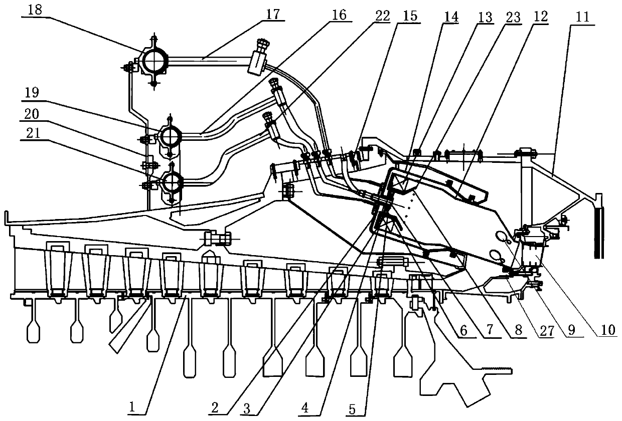
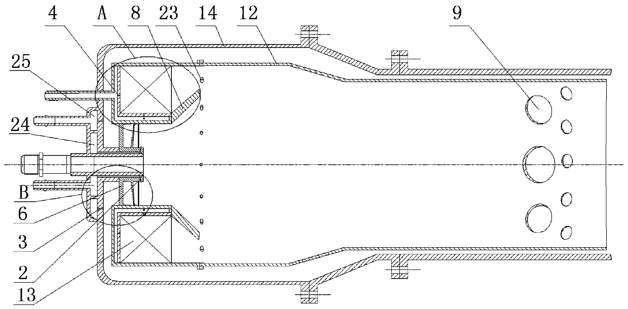
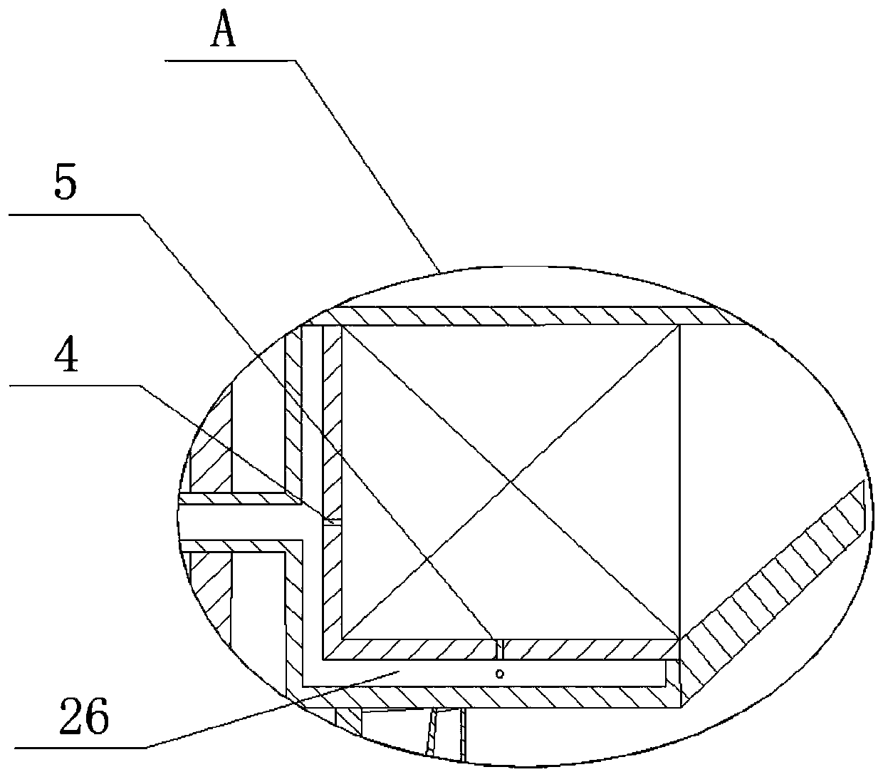
[0033] like Figure 1-Figure 4 As shown, a gas turbine low-emission combustor using gas fuel, the combustor head includes a duty stage and a main combustion stage arranged in a concentric manner, and the duty stage is in the center, and the main combustion stage is arranged at the periphery of the duty stage. Combustion stability and low emissions when using gaseous fuel is achieved by adjusting the fuel distribution of the duty stage, the main combustion stage including the first-stage axial swirler 6 and the duty stage fuel nozzles and the coordination between the different nozzles , the first-stage axial swirler 6 is installed in the central hole of the head of the flame tube 12, the outer casing 14 of the flame tube is installed outside the flame tube 12, and the flame tube 12 is arranged coaxially with the outer casing 14 of the flame tube, The outer casing 14 of the flame cylinder is respectively provided with a No. 1 duty fuel tank 24 and a No. 2 duty grade fuel tank 25...

Embodiment 2

[0039] like Figure 5 and Image 6 As shown, the outer casing 14 of the flame tube is located in the outer ring part of the high-pressure igniter 7 and close to one end of the first-stage axial swirler 6. The No. 2 duty fuel nozzles 3 are evenly arranged in the circumferential direction, and the No. The axial angle between the axis of the nozzle 3 and the first-stage axial swirler 6 is 60°. Other structures and connection methods are the same as those in Embodiment 1.

Embodiment 3

[0041] The installation angle between the center line of the flame tube 12 and the engine center line is 30°. Other structures and connection methods are the same as those in Embodiment 1 or Embodiment 2.


PUM


Abstract

The invention discloses a gas turbine low-emission combustion chamber using gas fuels, and belongs to the technical field of gas turbines. The combustion chamber comprises an on-duty grade, a main combustion grade, a high-pressure igniter, a mixing hole, an exhaust outlet, a bearing machine box, a flame cylinder, the flame cylinder outer machine box, a flange, a first on-duty grade gas fuel pipeline, a main combustion grade gas fuel pipeline, a main combustion grade fuel main pipe, a first on-duty grade fuel main pipe, a pipeline bracket, a second on-duty grade fuel main pipe, a second on-dutygrade gas fuel pipeline, an air conditioning device, a first on-duty grade fuel tank, a second on-duty grade fuel tank and a main combustion grade fuel tank; when a gas turbine is started in low-loadstates, only the on-duty grade works; when the gas turbine is started in high-load states, the on-duty grade and the main combustion grade work together; and through diffusion combustion of on-duty grade fuels, a stable ignition source is provided to a main combustion area, so that the low emission requirement is guaranteed, the combustion stability and the combustion efficiency are fully considered, and the performance requirements of the combustion chamber are comprehensively met.

Description

technical field [0001] The invention belongs to the technical field of gas turbine combustion chambers, and in particular relates to a gas turbine low-emission combustion chamber using gas fuel. Background technique [0002] The gas turbine originated in the 1960s. It can use various fuels such as gas fuel and liquid fuel. It has the advantages of high thermal efficiency, low pollution emission, small size, fast starting, less water consumption and suitable for burning a variety of fuels. countries' attention. It is a kind of power machinery widely used in aviation, ships, electric power and many other industrial fields, and plays a vital role in the development of the national economy. Compared with other engines, gas turbines have many advantages, such as fuel consumption rate, noise, emissions, vibration and other aspects. They can be used for traditional distributed power generation, and can also be used for grid-connected power generation. way, it is suitable for both...

Claims


Application Information

Patent Timeline
Patent Type & Authority Patents(China)
IPC IPC(8): F23R3/28F23R3/38
CPCF23R3/286F23R3/38
Inventor 刘爱虢李昱泽陈炫任曾文刘凯
Owner SHENYANG AEROSPACE UNIVERSITY
Why Eureka
Try Eureka