Radiation unit of electronic device and electronic device using same

a technology of electronic devices and radiation units, which is applied in the direction of cooling/ventilation/heating modifications, television system details, television systems, etc., can solve the problems of insufficient heat radiation behind the display unit and inside the control unit in the body case, and the television receiver is too heavy to be installed at high points outside, so as to achieve the effect of radiating hea

Inactive Publication Date: 2012-09-20
PANASONIC CORP
View PDF30 Cites 49 Cited by
  • Summary
  • Abstract
  • Description
  • Claims
  • Application Information

AI Technical Summary

Benefits of technology

[0010]With this structure, the blower blows the heat generated in the electronic device to the heat exchanger outside the electronic device, thereby effectively radiating the heat. The heat exchanger is formed of lightweight hot-air passage bodies, allowing both the cooling unit and the electronic device including the cooling unit to be lightweight.

Problems solved by technology

This sealing structure, however, cannot provide sufficient heat radiation behind the display unit and inside the control unit in the body case.
As well known, however, a plurality of metal fins disposed both inside and outside a metal partition board are very heavy, causing television receivers to be too heavy to be installed at high points outdoors.

Method used


Image

  • Radiation unit of electronic device and electronic device using same
  • Radiation unit of electronic device and electronic device using same
  • Radiation unit of electronic device and electronic device using same

Examples


first exemplary embodiment

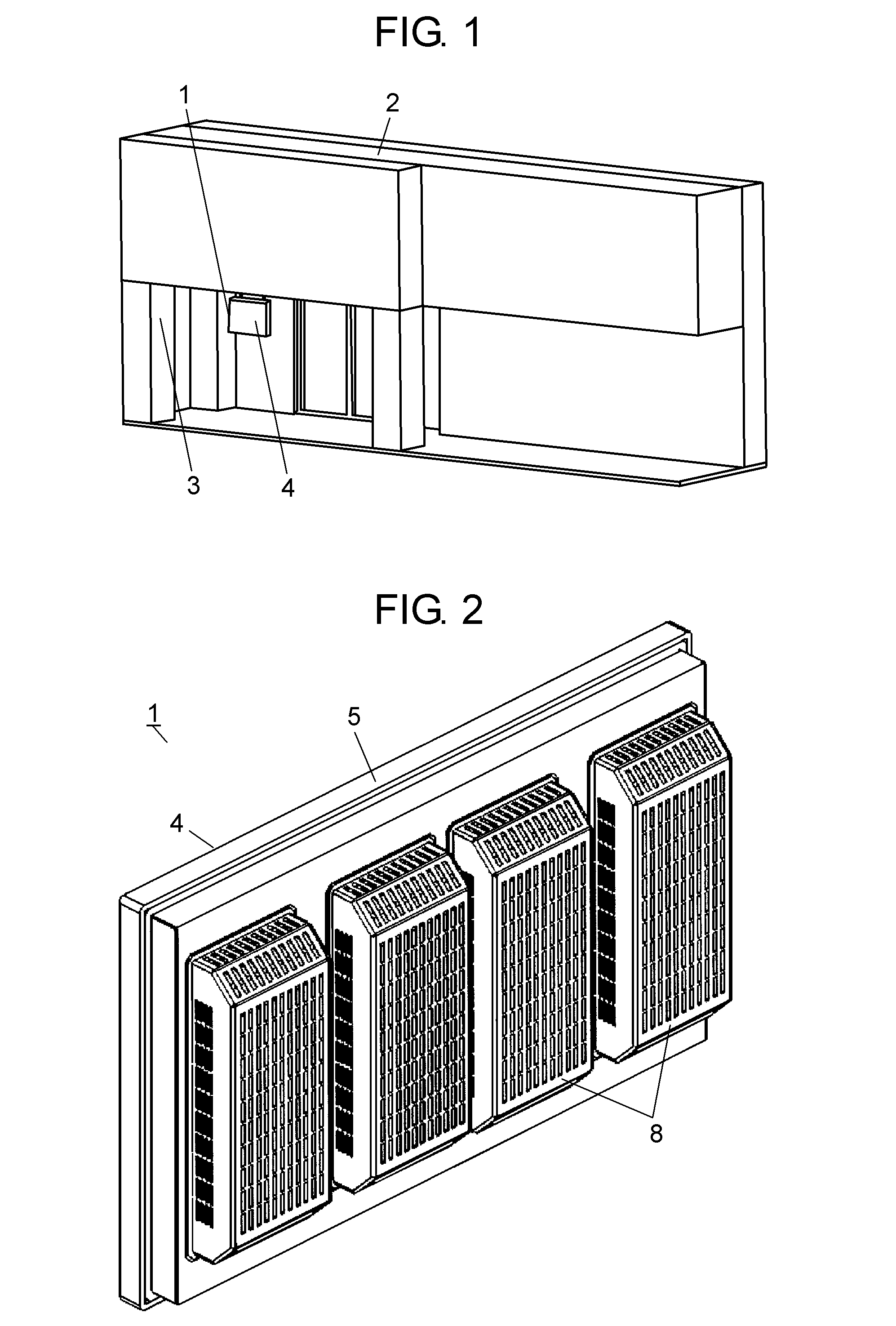
[0109]FIG. 1 is a perspective view of an example of installation of an electronic device according to a first exemplary embodiment of the present invention. Display device 1, which is an example of the electronic device, can be used to display advertisement outdoors in addition to functioning as a television receiver.

[0110]In FIG. 1, display device 1 is installed outdoors, namely, under the eaves 3 of shop 2. Display device 1 has display unit 4 on its front side. Display unit 4 has a horizontally long rectangular shape (a quadrate). As mentioned above, the “front” is the side on which display unit 4 is disposed in display device 1, and the “back” is the side which is opposite to display unit 4 in display device 1.

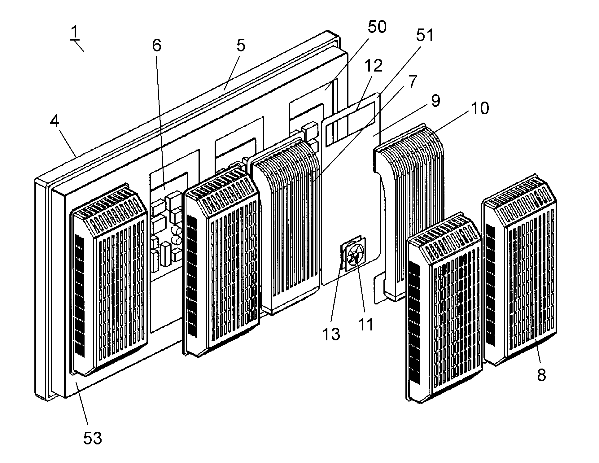
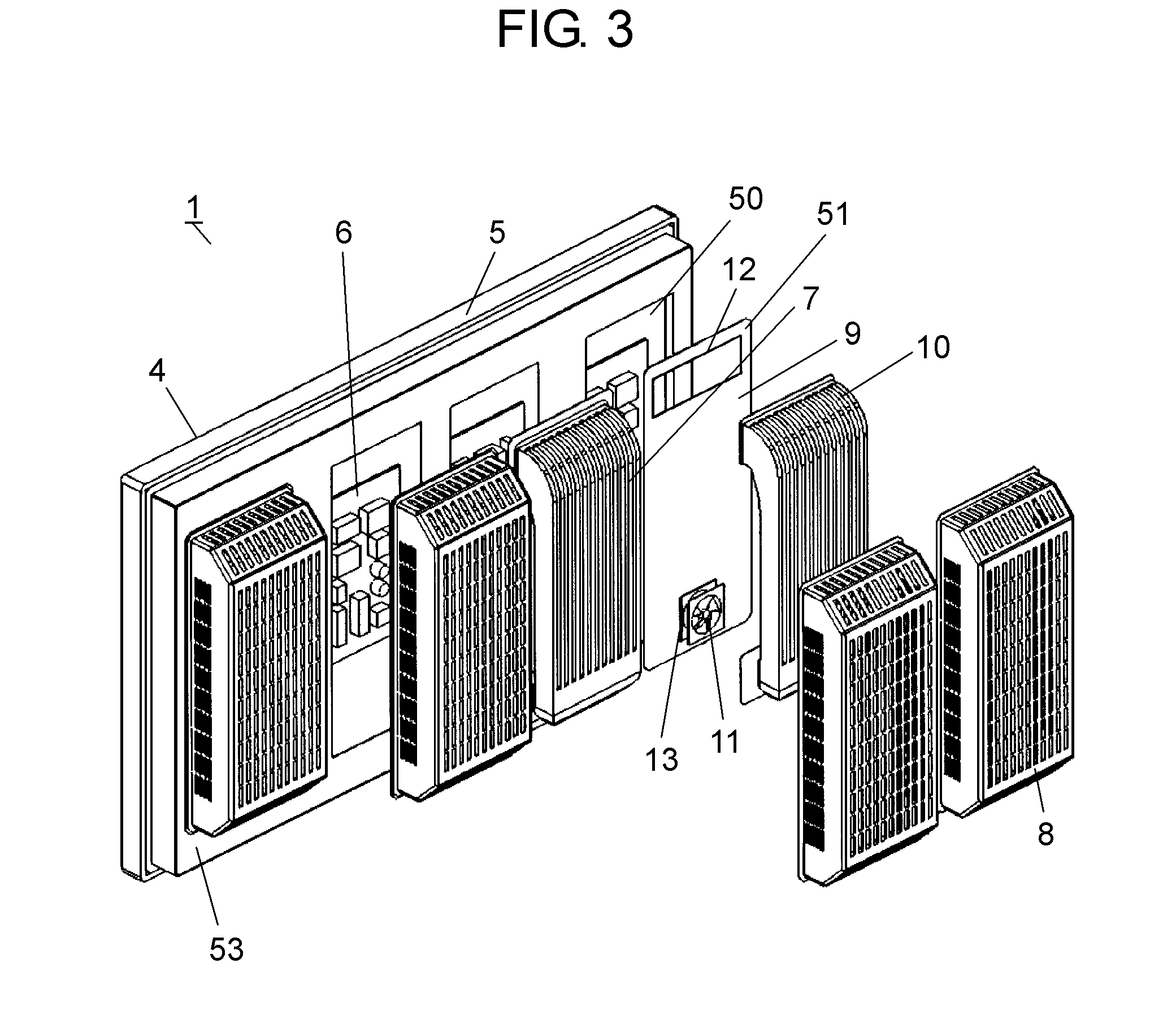
[0111]FIG. 2 is a rear perspective view of the electronic device according to the first exemplary embodiment, and FIG. 3 is an exploded rear perspective view of the electronic device. As shown in FIGS. 2 and 3, display device 1, which has a plurality of surfaces, includes b...

second exemplary embodiment

[0136]In a second exemplary embodiment of the present invention, the same components as in the first exemplary embodiment are denoted by the same reference numerals, and hence the description thereof will be omitted. The following description will be focused on the differences.

[0137]FIG. 8 is a rear perspective view of a cooling unit of an electronic device according to the second exemplary embodiment. FIGS. 9A, 9B, 9C, and 9D are front, top, side, and bottom views, respectively, of a cooling unit of the electronic device.

[0138]As shown in FIG. 8 and FIGS. 9A through 9D, in each heat exchanger 10, air pathways 15 formed along hot-air passage bodies 14 decrease in length with distance from the center of connection surface 54.

[0139]As a result, all air pathways 15 have the same length between upper vent 12 and lower vent 13, thereby equalizing the amount of air flowing through all hot-air passage bodies 14. This increases the heat exchange efficiency of the entire heat exchanger 10.

third exemplary embodiment

[0140]In a third exemplary embodiment of the present invention, the same components as in the first exemplary embodiment are denoted by the same reference numerals, and hence the description thereof will be omitted. The following description will be focused on the differences.

[0141]FIG. 10 is a rear perspective view of a cooling unit of an electronic device according to the third exemplary embodiment. FIGS. 11A, 11B, 11C, and 11D are front, top, side, and bottom views, respectively, of a cooling unit of the electronic device.

[0142]As shown in FIG. 10 and FIGS. 11A through 11D, in each heat exchanger 10, air passages 52 of hot-air passage bodies 14 are combined into one in lower collecting duct 14a. Lower collecting duct 14a is provided with projections and recesses, which correspond to the shape of air passages 52 of hot-air passage bodies 14 and the shape of air pathways 15, respectively. When a cooling unit 7 is seen in the cross section orthogonal to the direction in which the ai...


PUM


Abstract

A cooling unit includes a partition board, a heat exchanger, and a blower. The partition board is disposed on one of a plurality of surfaces of an electronic device so as to partition the inner and the outer side of the electronic device. The heat exchanger is disposed on the outer side so as to exchange heat generated by the electronic device with outside air. The blower is disposed on the outer side. The heat exchanger includes hot-air passage bodies and air pathways. The hot-air passage bodies include a plurality of air passages arranged side by side at predetermined intervals in such a manner as to connect a first vent and a second vent of the partition board on the outer side. The blower blows air of the inner side from the first vent to the second vent through the hot-air passage bodies.

Description

TECHNICAL FIELD[0001]The present invention relates to a cooling unit for electronic devices, and an electronic device including the cooling unit.BACKGROUND OF THE INVENTION[0002]Electronic devices such as television receivers have a display unit on the front side of the body case, and the control unit of the display unit inside the body case. The back surface of the control unit is closed by a partition board. These electronic devices are often suspended from the ceiling (see, for example, Patent Literature 1).[0003]Television receivers have been equipped with increasingly large display units in recent years, and there have been efforts to install them outdoors as advertising devices by making good use of their visual effects.[0004]Television receivers used outdoors need to be configured to protect the body case from rain infiltration. For this purpose, the front and back openings of the body case are sealed by the display unit and the partition board, respectively.[0005]This sealin...

Claims


Application Information

Patent Timeline
Patent Type & Authority Applications(United States)
IPC IPC(8): H05K7/20
CPCH05K7/20972H04N5/64H05K7/20
Inventor MURAYAMA, TAKUYAWAKAMATSU, TOMONORISUGIYAMA, MAKOTOKATSUMI, YOSHIMASAMIYAKE, SHUNJI
Owner PANASONIC CORP
Why Eureka
Try Eureka