Power Transfer Unit Shaft Input

a technology of power transfer unit and shaft input, which is applied in the direction of mechanical equipment, transportation and packaging, and transportation, etc., can solve the problems of vehicle transmission not providing a low enough drive ratio to enable a very low range drive ratio, and the existing power transfer unit exhibits a full time drain of fuel efficiency. , to achieve the effect of reducing the rate, reducing the rate, and reducing the rotation ra

Active Publication Date: 2012-09-20
GKN DRIVELINE NORTH AMERICA
View PDF2 Cites 12 Cited by
  • Summary
  • Abstract
  • Description
  • Claims
  • Application Information

AI Technical Summary

Benefits of technology

[0011]The power transfer final drive unit may provide torque to the front power transfer unit during synchronization prior to activating a mode shift. When the vehicle drive train is in operation and the wheels are spinning a request may be made by a computer module to engage the system, which results in engaging the electronic motor to activate and engage the final drive unit's mode selection and range selection assemblies. The computer module may have a predetermined algorithm based on certain operating conditions, which allows a synchronized activation. Activation of the assemblies provides a reverse engagement causing the hypoid gear assembly to rotate at a reduced rate as compared to the wheel speed. This reduced rate is a result of an RPM delta across the friction plates. The reduced rate of rotation in the hypoid gear assembly helps to synchronize the activation of the mode selection in the front power transfer unit. Thus, the final drive unit transfers torque to the front power transfer unit during synchronization, and then the front power transfer unit transfers torque to the final drive unit during a traction request event.
[0012]The exemplary arrangement provides that the internal mode selection and range selection provide design flexibility in terms of packaging constraints. In addition, by activating the mode prior to the differential, the amount of stress placed on the system is minimized while improving efficiency. Furthermore, it is contemplated that the torque flow from the power transfer unit to the power transfer final drive unit and the torque flow from the final drive unit to the power transfer unit are unique.

Problems solved by technology

However, in this “ready state”, the existing power transfer units exhibit a full time drain to fuel efficiency with only a part-time benefit
In vehicles where it is desirable to provide a very low range (creep) drive mode, however, the vehicle transmission may not provide a low enough drive ratio to enable a very low range drive ratio.

Method used


Image

  • Power Transfer Unit Shaft Input
  • Power Transfer Unit Shaft Input
  • Power Transfer Unit Shaft Input

Examples


Embodiment Construction

[0029]In the following description, various operating parameters and components are described for one exemplary constructed embodiment. These specific parameters and components are included as examples, but are not meant to be limiting.

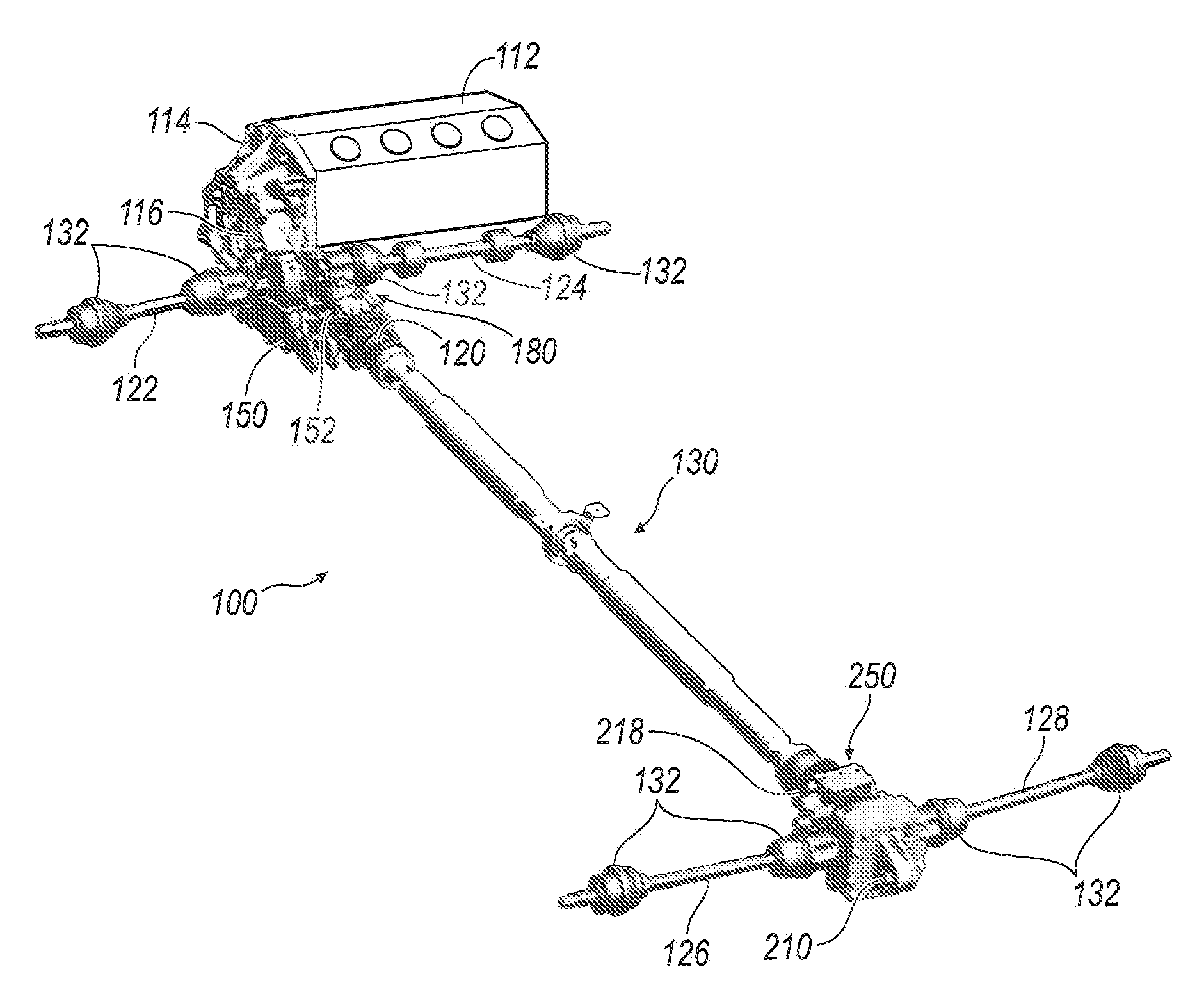
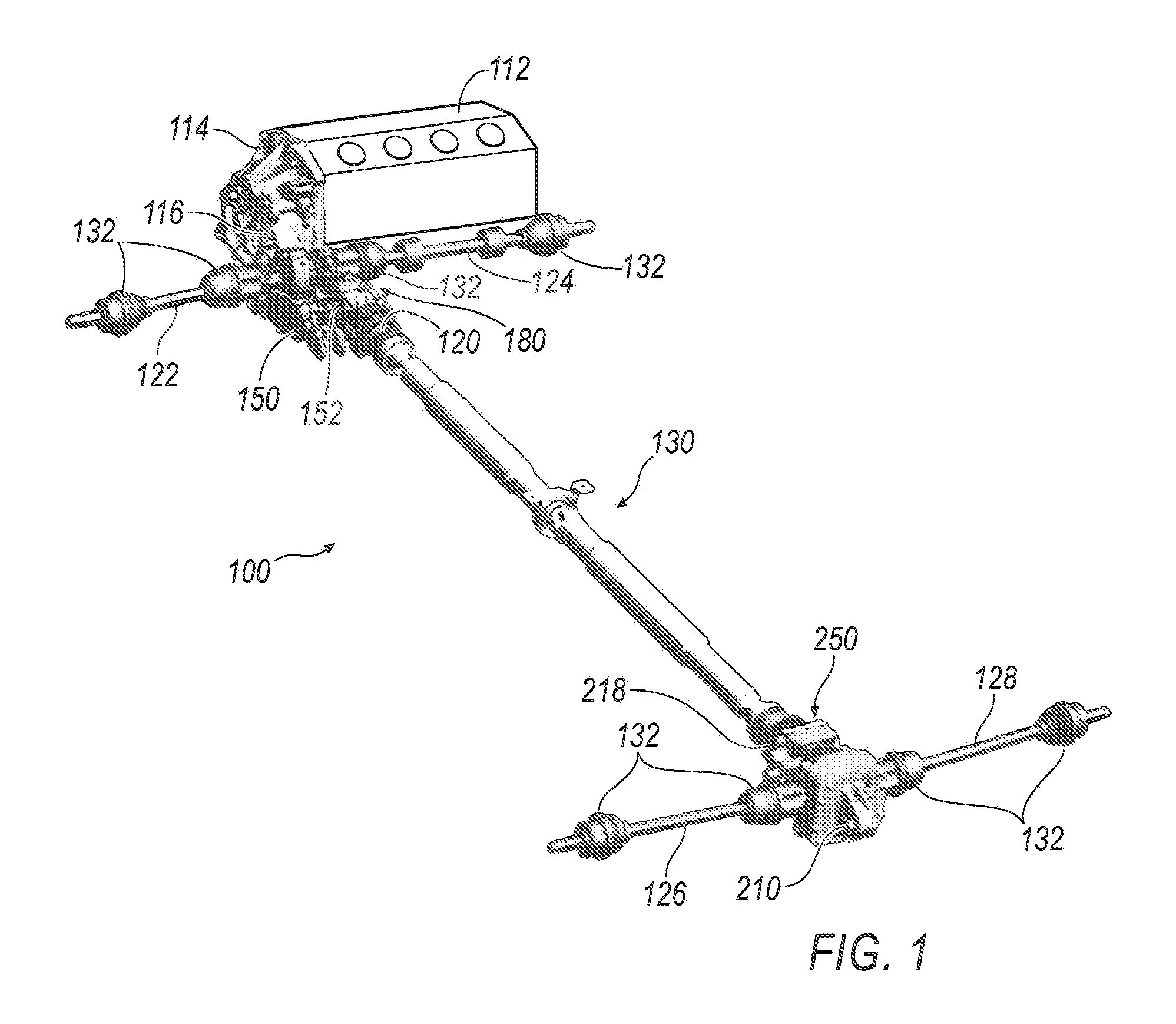
[0030]Referring now to FIG. 1, an exemplary vehicle drive train assembly 100 is illustrated. The vehicle drive train assembly 100 is illustrated having a transversely mounted engine 112 and transmission 114. The vehicle drive train assembly 100 may include a plurality of shaft elements 122, 124, 126, 128 and corresponding articulating torque transfer joints , which are illustrated as a constant velocity joints 132. The shaft elements 122, 124, 126, 128 and joints 132 may be used to transmit torque from a power transfer unit 150 to a plurality of wheels (not shown). The wheels are generally positioned at an outer end of the shaft elements 122, 124, 126, 128, which provide power to drive the wheels. Generally, the engine 112 may be affixed to a transmis...


PUM


Abstract

A power transfer unit assembly for a vehicle. The power transfer unit includes a housing, an internal variable speed differential positioned within the housing, a first front side shaft rotatively connected to the differential, a second front side shaft rotatively connected to the differential, an input shaft interconnected to at least one of the first and second side shafts, and at least one shifting mechanism for engaging at least one of the first and second shafts with at least one mode selection gear set. Engagement of the mode selection gear set transfers torque through the input shaft to selectively engage with a second gear set interconnected to a power transfer final drive unit assembly having an internal variable speed differential.

Description

CROSS-REFERENCE TO RELATED APPLICATIONS[0001]This application claims priority to U.S. Provisional Application Nos. 61 / 265,959, filed on Dec. 2, 2009, and 61 / 297,498, filed on Jan. 22, 2010, all of which are hereby incorporated herein by reference in their entirety.TECHNICAL FIELD[0002]The disclosure generally relates to power transfer units and more particularly, to power transfer units with integrated differential and shaft inputs for shifting between two-wheel-drive to all-wheel or four-wheel drive modes.BACKGROUND OF THE INVENTION[0003]Fuel and driveline efficiency is a controlling factor in the design of vehicle components. Specifically, designers of all-wheel drive and four-wheel drive vehicles weigh fuel efficiency for daily driving against performance in extreme roadway or off-highway conditions. Motor vehicles are driven by a transmission that transmits rotational torque to a power transfer unit (also known as a power take-off unit) through a torque transmitting shaft. The p...

Claims


Application Information

Patent Timeline
Patent Type & Authority Applications(United States)
IPC IPC(8): F16H48/30
CPCB60K23/08F16H48/10F16H48/08B60K17/344
Inventor PEURA, BRENT MICHAELGENWAY-HADEN, ROBERTGASSMANN, THEODORSCHMIDT, MARKSCHWEKUTSCH, MICHAEL
Owner GKN DRIVELINE NORTH AMERICA
Why Eureka
Try Eureka