
Method and apparatus for delivering an implant without bias to a left atrial appendage

a left atrial appendage and left atrial technology, applied in the field of left atrial appendage delivery without bias, can solve the problems of irregular and turbulent blood flow in the vascular system, rapid and chaotic heartbeat, and failure to contract with any vigor, so as to reduce, eliminate, and/or eliminate the effect of implantation bias

Inactive Publication Date: 2012-09-20
ATRITECH INC
View PDF0 Cites 36 Cited by
  • Summary
  • Abstract
  • Description
  • Claims
  • Application Information

AI Technical Summary

Benefits of technology

[0008]There is provided in accordance with one embodiment of the present invention a system and method for minimizing, reducing, substantially eliminating, and / or eliminating implantation bias during delivery of an implant. The system includes an implant with a distal guide tube, an actuation shaft, and a concentrically attachable disconnect mount. In one embodiment the implant is configured to contain emboli with a left atrial appendage of a heart of a patient. The implantable device has a proximal and distal end with a plurality of supports and is moveable between a collapsed and an expanded configuration. The distal guide tube at the distal end of the supports extends toward the proximal end of the implant. The actuation shaft extends through the proximal end of the implantable device and is removeably engageable with the distal guide tube. The disconnect mount is releasably engageable with the proximal end of the implant and is concentrically attachable to the proximal end of the implant. In one embodiment, the implant is self-expandable. In another embodiment, the implant is collapsed by engaging the actuation shaft with the distal guide tube while applying a relatively proximal force to the proximal end of the implant with the disconnect mount.

Problems solved by technology

Embolic stroke is the nation's third leading killer for adults, and is a major cause of disability.
Atrial fibrillation is an arrhythmia of the heart that results in a rapid and chaotic heartbeat that produces lower cardiac output and irregular and turbulent blood flow in the vascular system.
A patient with atrial fibrillation typically has a significantly decreased quality of life due, in part, to the fear of a stroke, and the pharmaceutical regimen necessary to reduce that risk.
The LAA normally contracts with the rest of the left atrium during a normal heart cycle, thus keeping blood from becoming stagnant therein, but often fails to contract with any vigor in patients experiencing atrial fibrillation due to the discoordinate electrical signals associated with atrial fibrillation.
Pharmacological therapies for stroke prevention such as oral or systemic administration of warfarin or the like have been inadequate due to serious side effects of the medications and lack of patient compliance in taking the medication.
Invasive surgical or thorascopic techniques have been used to obliterate the LAA, however, many patients are not suitable candidates for such surgical procedures due to a compromised condition or having previously undergone cardiac surgery.
In addition, the perceived risks of even a thorascopic surgical procedure often outweigh the potential benefits.
The thrombus in the blood stream of the patient can cause embolic stroke.
Unfortunately, using staples or sutures to close off the LAA may not completely close the orifice of the LAA.
Additionally, closing the orifice of the LAA by using staples or sutures may result in discontinuities, such as folds or creases, in the endocardial surface facing the left atrium.
Unfortunately, blood clots may form in these discontinuities and can enter the patient's blood stream, thereby causing health problems.
Moreover, it is difficult to place sutures at the orifice of the LAA and may result in a residual appendage.
For example, an epicardial approach to ligate sutures can result in a residual appendage.
Similarly, thrombus may form in the residual appendage and enter the patient's blood stream causing health problems.
However, some delivery devices can have limited flexibility and can provide off-axis loading that creates moment arms and bending bias.

Method used


Image

  • Method and apparatus for delivering an implant without bias to a left atrial appendage
  • Method and apparatus for delivering an implant without bias to a left atrial appendage
  • Method and apparatus for delivering an implant without bias to a left atrial appendage

Examples


Embodiment Construction

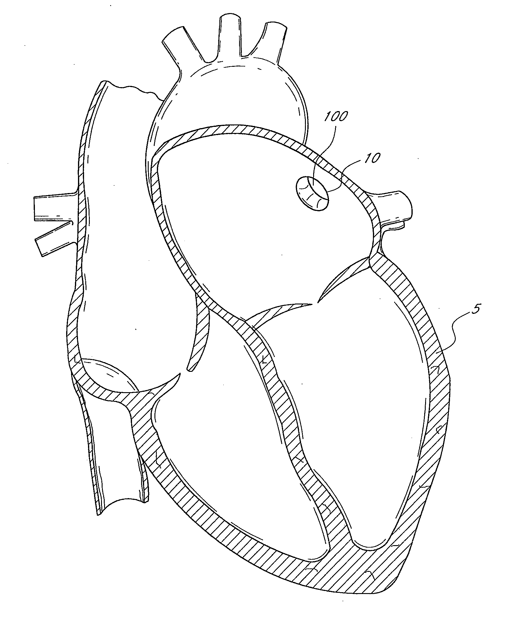
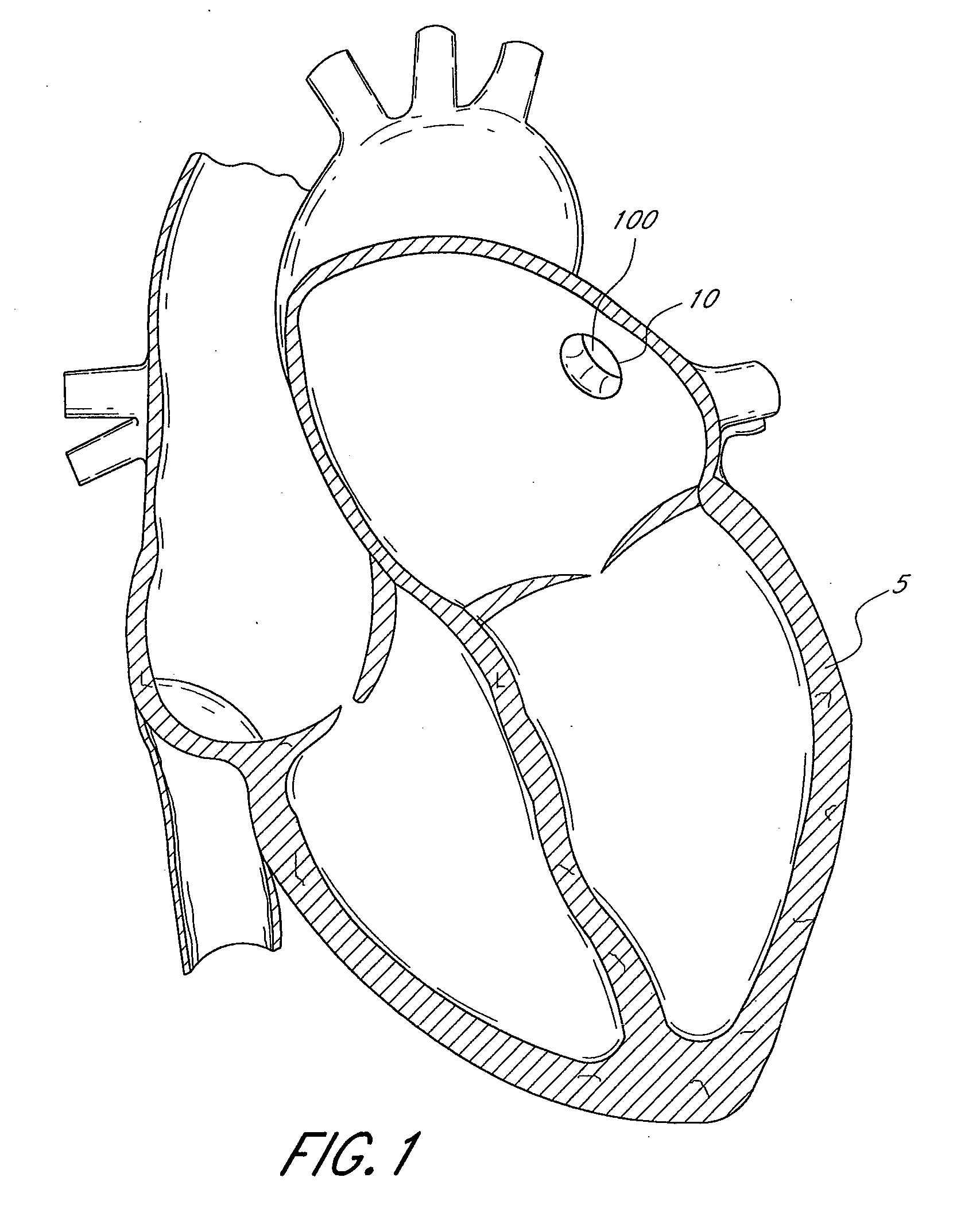
[0063]FIG. 1 illustrates a sectional view of a heart 5 and its left atrial appendage (LAA) 10. An implant 100 is provided at least partially within the LAA 10. The terms “implant”, “occlusion device” or “containment device” are broad terms intended to have their ordinary meaning. In addition, these terms are intended to refer to devices that are inserted into the body. Such devices may include a membrane, barrier and / or cover, or may omit these portions. Embodiments of the invention may also be used to treat other bodily openings, lumen and cavities, besides the LAA 10. For example, in some embodiments, the methods, devices and systems described herein are used to treat any heart opening or defect, such as a patent foramen ovale (PFO), an atrial septal defect (ASD), a ventricular septal defect (VSD), a patent ductus arteriosus (PDA), an aneurysm and / or an aortico-pulmonary window.

[0064]In various embodiments, an implant 100 can be delivered in a number of ways, e.g., using conventio...


PUM


Abstract

An implant delivery system, comprising: an implantable device comprising a plurality of supports extending between a proximal end and a distal end, the supports being moveable between a collapsed configuration and an expanded configuration, a proximal guide tube at the proximal end of the supports extending toward the distal end, and a distal guide tube at the distal end of the supports extending toward the proximal end, wherein the proximal and distal guide tubes are telescoping and become further engaged as the supports move from the collapsed to the expanded configuration.

Description

CROSS-REFERENCE TO RELATED U.S. APPLICATIONS[0001]This application claims the benefit of priority from U.S. Provisional No. 60 / 741,111, filed Dec. 1, 2005, which is incorporated by reference, herein.BACKGROUND[0002]Embolic stroke is the nation's third leading killer for adults, and is a major cause of disability. There are over 700,000 strokes per year in the United States alone. Of these, roughly 100,000 are hemorrhagic, and 600,000 are ischemic (either due to vessel narrowing or to embolism). The most common cause of embolic stroke emanating from the heart is thrombus formation due to atrial fibrillation. Approximately 80,000 strokes per year are attributable to atrial fibrillation. Atrial fibrillation is an arrhythmia of the heart that results in a rapid and chaotic heartbeat that produces lower cardiac output and irregular and turbulent blood flow in the vascular system. There are over five million people worldwide with atrial fibrillation, with about four hundred thousand new c...

Claims


Application Information

Patent Timeline
Patent Type & Authority Applications(United States)
IPC IPC(8): A61F2/01
CPCA61B17/0057A61B2017/12095A61B17/12122A61B17/12172A61B2017/00477A61B2017/00575A61B2017/00579A61B2017/00592A61B2017/00597A61B2017/00619A61B2017/00623A61B2017/00632A61B2017/00986A61B2017/0412A61B2017/0427A61B2017/0464A61B2017/22038A61B2017/12054A61B17/12022A61F2/01A61F2/011A61B2017/1205
Inventor ZAVER, STEVEANDERSON, KEVINCOWDEN, KEVINQUINN, CHRISWATSCHKE, BRIAN
Owner ATRITECH INC
Learn More