Toilet Flange Assembly With Cover

a technology for toilet flanges and covers, which is applied in water closets, water installations, construction, etc., can solve the problems of increasing the structural integrity of toilet flanges and saving manufacturing costs, and achieves the effects of convenient reattachment, convenient placement, and easy removal

Inactive Publication Date: 2012-09-27
YSSEL ERIKA
View PDF10 Cites 20 Cited by
  • Summary
  • Abstract
  • Description
  • Claims
  • Application Information

AI Technical Summary

Benefits of technology

[0009]It is the object of the present invention to form a toilet flange with several improvements over conventional toilet flanges. One aspect of the invention is to form a toilet flange with a removable cover wherein the cover performs multiple functions. The removable cover forms a storage compartment for the toilet fastening assembly elements. It also removably blocks the opening of the riser pipe to keep debris from entering the riser pipe when the cover is in place. The cover includes geometric indicators which define the centerline axes of the flange. The cover includes raised aligned spaced tabs which function as a backstop for placing a straightedge to more clearly define a parallel orientation to a finished wall surface. The raised tabs also function as elements onto which a measuring tape can be hooked to clearly measure the distance from the centerline to the finished wall surface. And, the cover functions to keep debris out of the openings into which the toilet fastening bolts will be threaded. The cover also interlocks with the fastening nuts into which the fastening bolts will be inserted. The cover interlocks with the nuts by hook-type flared end portions on the end of the male projections which are inserted into the nuts. This hook-type feature more securely retains the nuts to the flange during shipping and prior installation. By having a storage compartment built into the toilet flange cover the fastening assembly, which may include a pair of toilet fastening bolts with protective sleeves, fastening nuts and washers, is readily located when needed at the time of toilet installation. The removable cover blocks any debris from entering the riser pipe during the construction phase. The cover is easily removable, with the assistance of pry point recesses, for access to the riser drain pipe for verifying visually the water level within the riser pipe. The cover is also easily reattached after testing is completed by merely aligning the male projections formed on the underside of the cover with the toilet fastening bolt openings. In this manner the male projections now retain the nuts in place being centered and in alignment with the openings into which the fastening bolts will be inserted.
[0010]Another aspect of the invention is the toilet flange itself is formed with a straight portion along the perimeter outer surface so that the installer can readily determine when the toilet fastening bolts are aligned parallel relative to the finished walls near the toilet flange installation. The straight portion is symmetrical with respect to the two toilet fastening bolt openings. By making this straight portion parallel to the finished wall surface, in combination with flexible sleeves (discussed hereinbelow), there is no longer a need for any circumferential or radial slots in the toilet flange and there is no worry of chipping of the toilet base. No circumferential or radial adjustment is needed relative to any finished wall surface since the straight portion is parallel to the rear of the toilet tank and thus parallel to the finished wall surface and there is a clear indication in both directions of the distance to any wall. Since no adjustment of the toilet fastening bolt location is needed the slots in the top surface of the flange are replaced with a single pair of openings into which the toilet fastening bolts are inserted. This improved toilet flange configuration allows the flange screw apertures, for securing the flange to a floor surface, to be spaced further radially than conventional toilet flanges because the integrity of the flange is higher with less openings in the top surface. By spacing the flange screw apertures further apart the flange is more rigidly secured to the floor. Fastening the toilet flange more securely to the floor means a greater rocking force of the toilet would be required to dislodge the flange. This design further allows the floor joists to be spaced further from the riser pipe allowing easier access for securing the toilet flange to the riser during construction. It further allows the flange screws to bite into the floor joists beneath the plywood flooring. The preferred embodiment provides a reduction in the number of toilet fastener bolt locations to just the two needed. This increases the structural integrity of the toilet flange and saves manufacturing costs.
[0011]Another aspect of the invention is that each of the toilet fastening bolts is provided with a brightly colored disposable fitted sleeve that performs a double function. During the construction phase the sleeve provides an additional cover to keep the bolt threads clean while they are stored within the removable cover. During the time of toilet installation the sleeve is extended up to act as a flexible guide for the installer to align the bolt through the toilet base opening. The sleeves are flexible, disposable and brightly colored thus providing a bright contrast so that the toilet installer has a visual aid in aligning the openings in the toilet base with the flexible brightly colored sleeves. The fitted extendable sleeves nearly visually double the length of the toilet fastening bolts thus allowing the toilet installer twice the height off the floor to align the toilet base openings with the toilet bolts. The flexible sleeve eliminates the possibility of chipping the porcelain toilet base, of bending a toilet fastening bolt due to the toilet swinging motion during initial line-up and prevents toilet flange fracturing. The fastening bolt itself is also not rigidly connected to the toilet flange but is held securely erect by the threaded nut which acts as a purchase held firmly to the underside of the radial portion of the flange.
[0012]A further benefit of the invention is the elimination of one of the loose fastening elements. The invention eliminates the need of push-on bolt stabilizers.

Problems solved by technology

This increases the structural integrity of the toilet flange and saves manufacturing costs.

Method used


Image

  • Toilet Flange Assembly With Cover
  • Toilet Flange Assembly With Cover
  • Toilet Flange Assembly With Cover

Examples


Embodiment Construction

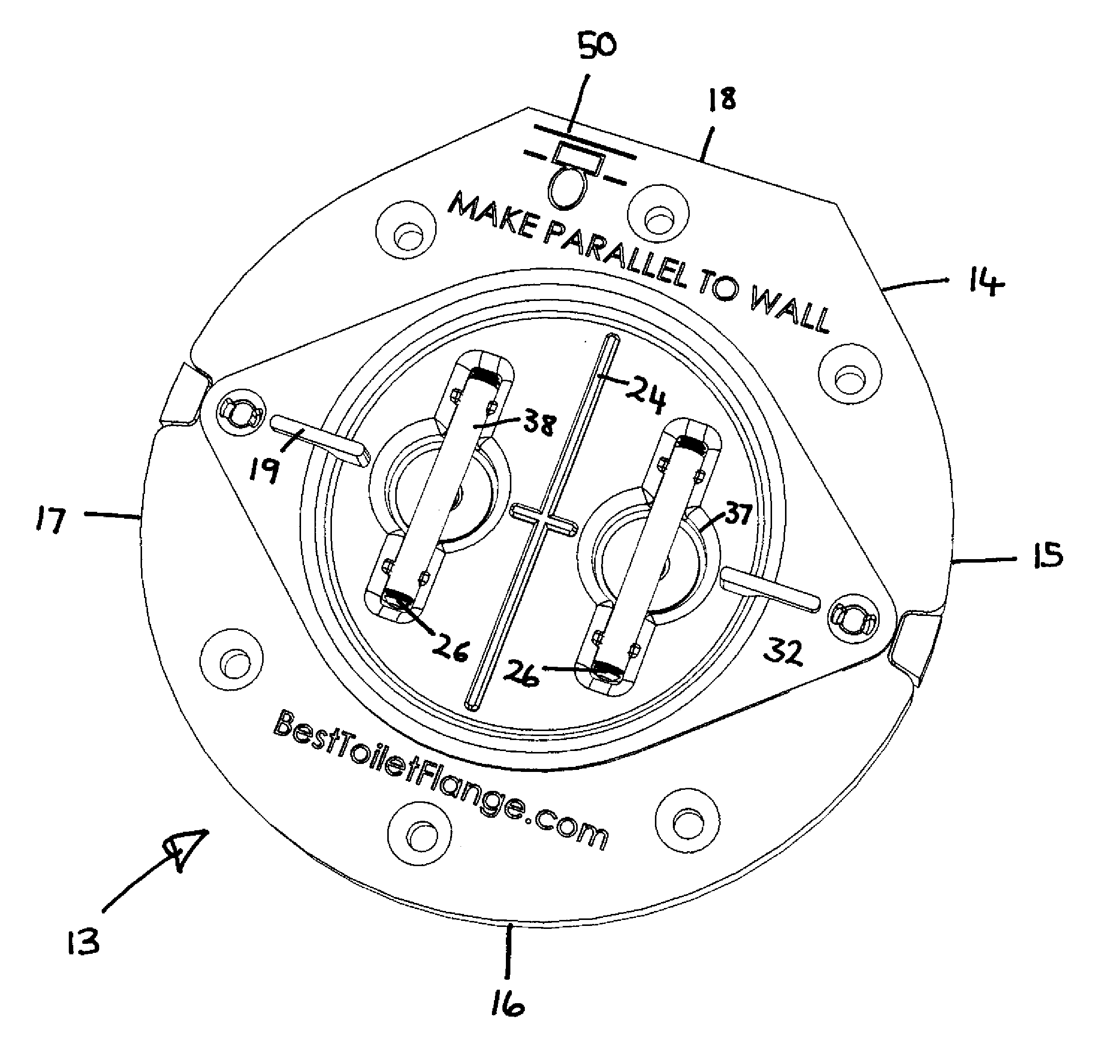
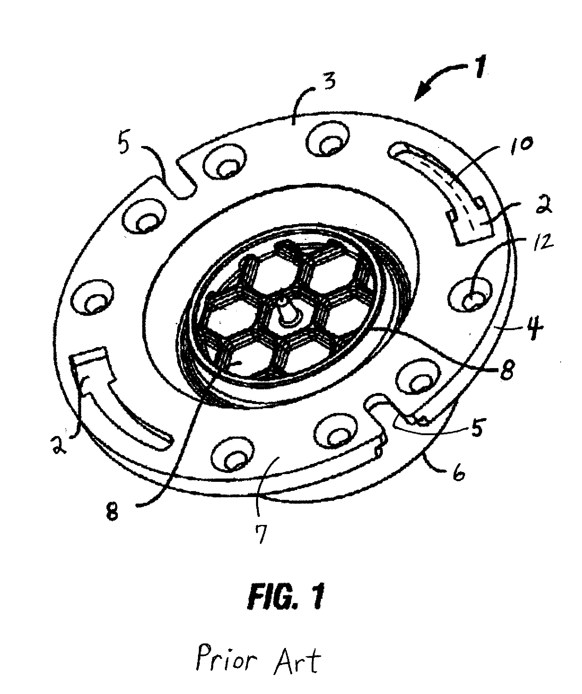
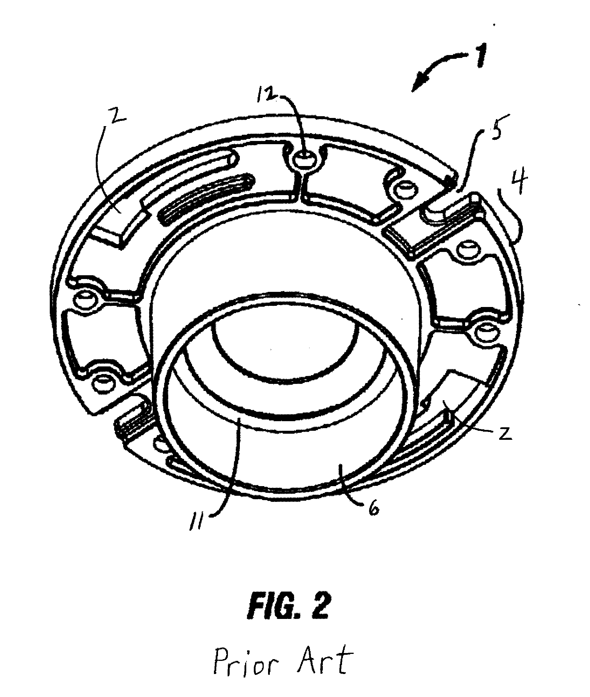
[0028]Referring to the drawings, wherein like reference numerals are used to designate like parts, FIG. 4 shows a preferred embodiment of the closet or toilet flange 13 in accordance with the present invention which comprises a body having an outer perimeter surface 14 which is shaped with rounded perimeter side portions 15, 16, 17 and at least one perimeter straight surface portion 18. The straight surface portion 18 is also planar in the plane perpendicular to the subfloor onto which the flange is secured so that a straightedge 55, such as a conventional level, can be abutted against the planar straight surface 18 to function as a visual aid (FIG. 11) in extending the line 20 (FIG. 5) of the straight portion 18 parallel to a future finished wall surface. The radial dimensions of the toilet flange are sized so that the perimeter rounded side portions 15-17 and the straight surface portion 18 properly fit within the recess of a conventional toilet base (not shown). Unlike convention...


PUM


Abstract

A toilet flange is provided with a planar perimeter portion to assist the installer in accurately determining the distance to an adjacent wall as well as insuring the toilet fastening bolts are aligned parallel thereto. The toilet flange assembly includes a cover to store needed fastening elements while simultaneously preventing debris from entering the plumbing riser pipe. Additionally, a sleeve is provided that protects the threads of the toilet fastening bolts during construction and acts as an extendable flexible guide sleeve. The guide sleeve functionally extends the height of the toilet fastening bolt thereby assisting the toilet installer as a visual aid during installation.

Description

CROSS REFERENCE TO RELATED APPLICATIONS[0001]This specification claims priority of the provisional U.S. patent application Ser. No. 61 / 457,405 filed on Mar. 21, 2011.FIELD OF THE INVENTION[0002]The invention relates to plumbing fittings and more particularly it relates to a toilet flange assembly for facilitating connection of a toilet to a waste riser pipe.BACKGROUND OF THE INVENTION[0003]In residential and commercial building construction it is necessary to connect the base of a toilet, usually made of porcelain or similar material, to a drain pipe in a secure and water tight manner that meets all plumbing codes applicable in the local jurisdiction. The most common way of achieving this connection is to utilize a closet or toilet flange. The conventional toilet flange (1; FIG. 1) has a generally flat upper surface 3 and round perimeter surface 4 and includes at least one pair of semi-circular diametrically opposed arcuate key-shaped slots 2 which extend circumferentially 10 and al...

Claims


Application Information

Patent Timeline
Patent Type & Authority Applications(United States)
IPC IPC(8): E03D11/14
CPCE03D11/16
Inventor YSSEL, ERIKA
Owner YSSEL ERIKA
Why Eureka
Try Eureka