Device to capture wave energy

Active Publication Date: 2012-09-27
OCILLO DRIVE HLDG LLC
View PDF7 Cites 4 Cited by
  • Summary
  • Abstract
  • Description
  • Claims
  • Application Information

AI Technical Summary

Benefits of technology

[0011]An output shaft is also rotatably mounted to the housing and is drivingly connected to an energy storage device or an electrical genera

Problems solved by technology

While the energy stored in the movement of water due to tidal variations is indeed large, the equipment necessary to harness that energy for the production of electrical power has proven to be costly not only to construct but also to maintain.
Furthermore, the movement of the water between high tide and low tide occurs only once per day on the average so that the energy in tidal water can only be harvested once per day, i.e. when the tide moves from high tide to low tide.
Because of these limitations, devices to harness energy from tidal movement of the oceans have not proven cost effective.
However, when waves are present, the waves rise and fall much more rapidly than the movement of water level due to tidal effects.
Previously, there have been no machines or devices which have effectively harnessed the energy from waves in a water body.

Method used


Image

  • Device to capture wave energy
  • Device to capture wave energy
  • Device to capture wave energy

Examples


Embodiment Construction

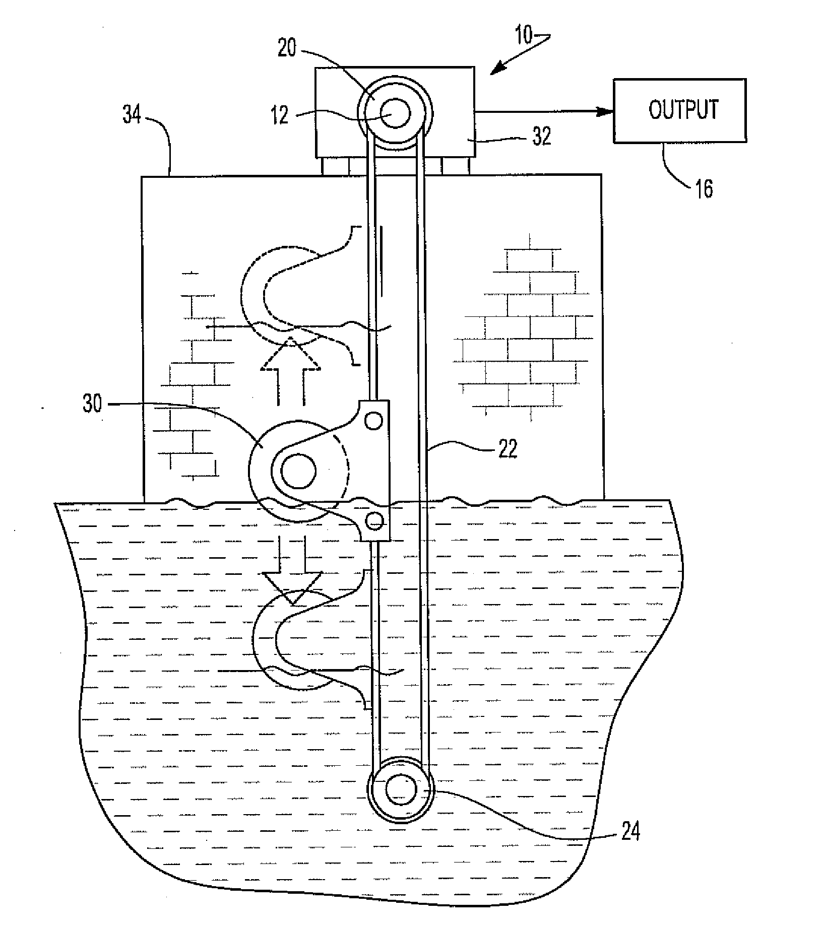
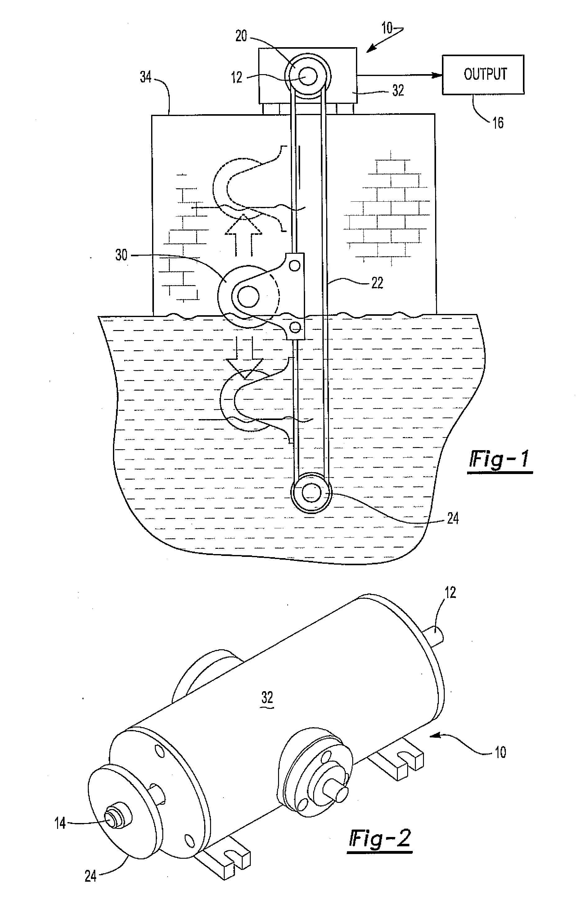
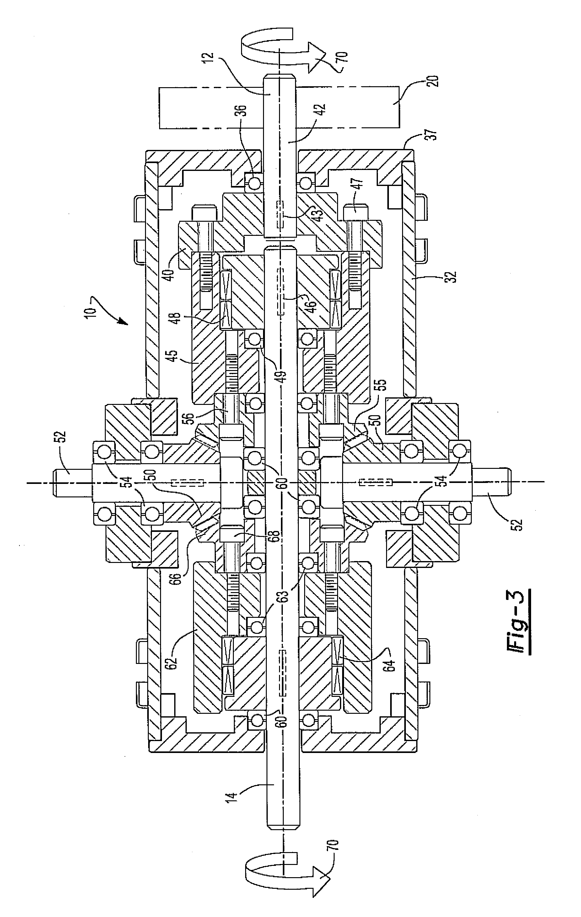
[0020]With reference first to FIGS. 1 and 2, a preferred embodiment of the device 10 for harvesting energy from variations in water level is shown. The device 10 includes an input shaft 12 and an output shaft 14. The output shaft 14 is connected to an energy storage / generator device 16 which stores or generates energy in response to rotation of the output shaft 14.

[0021]For example, the energy storage / generator device 16 may comprise a pump for pumping water to an elevated level for subsequent release through a generator. During that subsequent release, electric energy is generated. Alternatively, the storage / generator device 16 may comprise an electrical generator.

[0022]Referring now to FIG. 1, a gear wheel or pulley 20 (collectively called pulley) is attached to the input shaft 12 so that the pulley 20 rotates in unison with the input shaft 12. An endless chain or belt 22 (collectively called belt) is disposed around the pulley 20 so that the belt 22 is drivingly connected to the ...


PUM


Abstract

A device to capture and store or generate energy from variations in water level of a water body has a housing and an input shaft rotatably mounted to the housing. A drive belt is rotatably connected to the input shaft and a float is attached to that drive belt so that the float reciprocally drives the input shaft as the water levels increase and decrease. An output shaft is also rotatably mounted to the housing while a first one-way clutch is operatively disposed between the input shaft and the output shaft so that the input shaft rotatably drives the output shaft through the clutch in one rotational direction. A reversing gear is rotatably mounted to the housing and rotatably drives a second one-way clutch also operatively coupled to the second shaft to drive the second shaft in the same rotational direction as the first clutch, but during the opposite rotation of the input shaft.

Description

BACKGROUND OF THE INVENTION[0001]I. Field of the Invention[0002]The present invention relates to a device for capturing wave and / or tidal energy.[0003]II. Description of Related Art[0004]In view of the increasing cost of organic fuels, such as coal and oil, there has been a recent trend to harness energy for the generation of power from previously unharnessed or only marginally harnessed power sources. For example, wind turbines for generating electrical power from wind currents have enjoyed increased popularity.[0005]A still further source of previously unharnessed energy is the energy generated and consumed from the movement of water levels in water bodies. For example, there are previously known devices for harnessing the energy occurring through the movement of ocean tides.[0006]While the energy stored in the movement of water due to tidal variations is indeed large, the equipment necessary to harness that energy for the production of electrical power has proven to be costly not...

Claims


Application Information

Patent Timeline
IPC IPC(8): F03B13/12
CPCF03B13/1865Y10T74/1526Y02E10/38Y02E10/30
Inventor PADULA, PHILIP
Owner OCILLO DRIVE HLDG LLC
Why Eureka
Try Eureka