Edge banding machine

a banding machine and edge banding technology, which is applied in the field of edge banding machines, can solve the problems of uneven thickness of glue on the glue-applying roller, imposed work burden on subsequent operation, and inability to evenly adhere the edge band to the work pi

Active Publication Date: 2012-09-27
LIN CHIN CHI
View PDF2 Cites 20 Cited by
  • Summary
  • Abstract
  • Description
  • Claims
  • Application Information

AI Technical Summary

Benefits of technology

[0010]The effect of this invention is: due to the inclusion of the glue-scratching unit, glue on the glue-ap

Problems solved by technology

However, since the glue-applying roller is rotated to apply the glue from the glue container onto the surface of the edge band, the thickness of the glue on the glue-applying roller is non-uniform.
As a resul

Method used


Image

  • Edge banding machine
  • Edge banding machine
  • Edge banding machine

Examples


Embodiment Construction

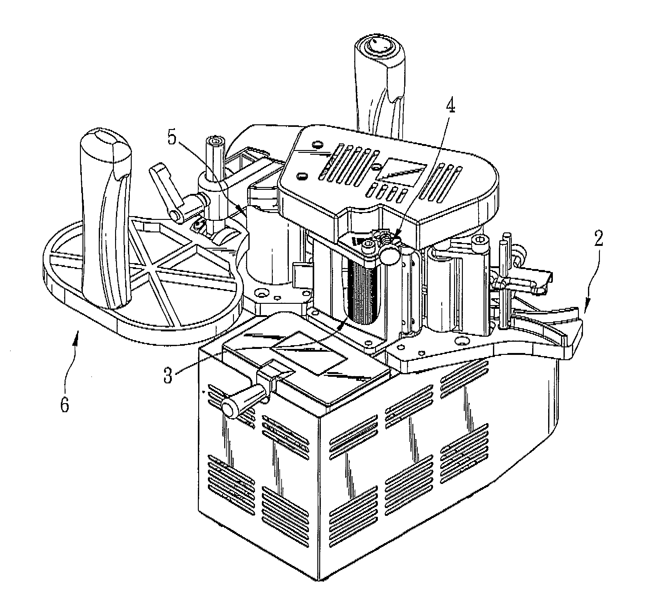
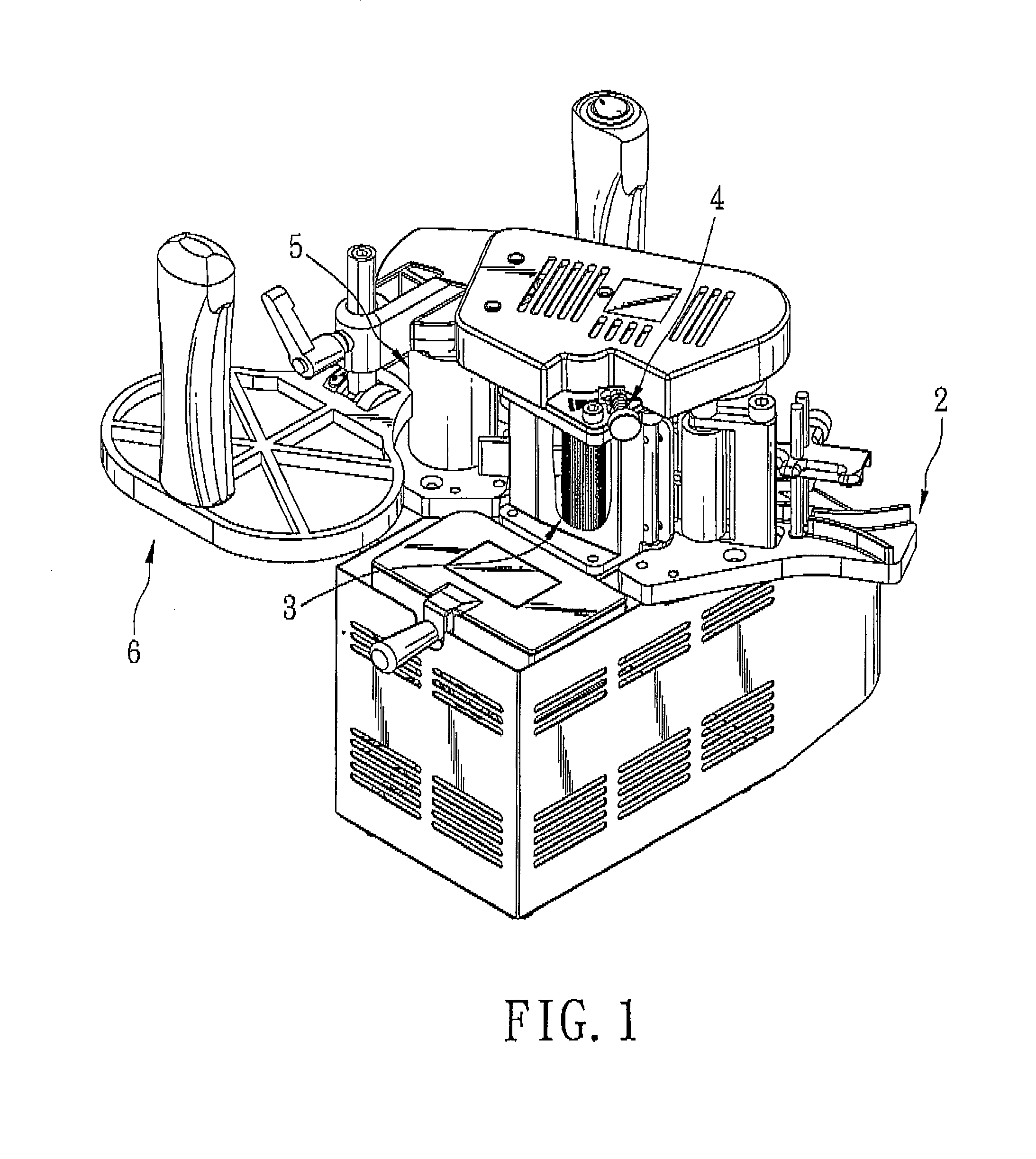
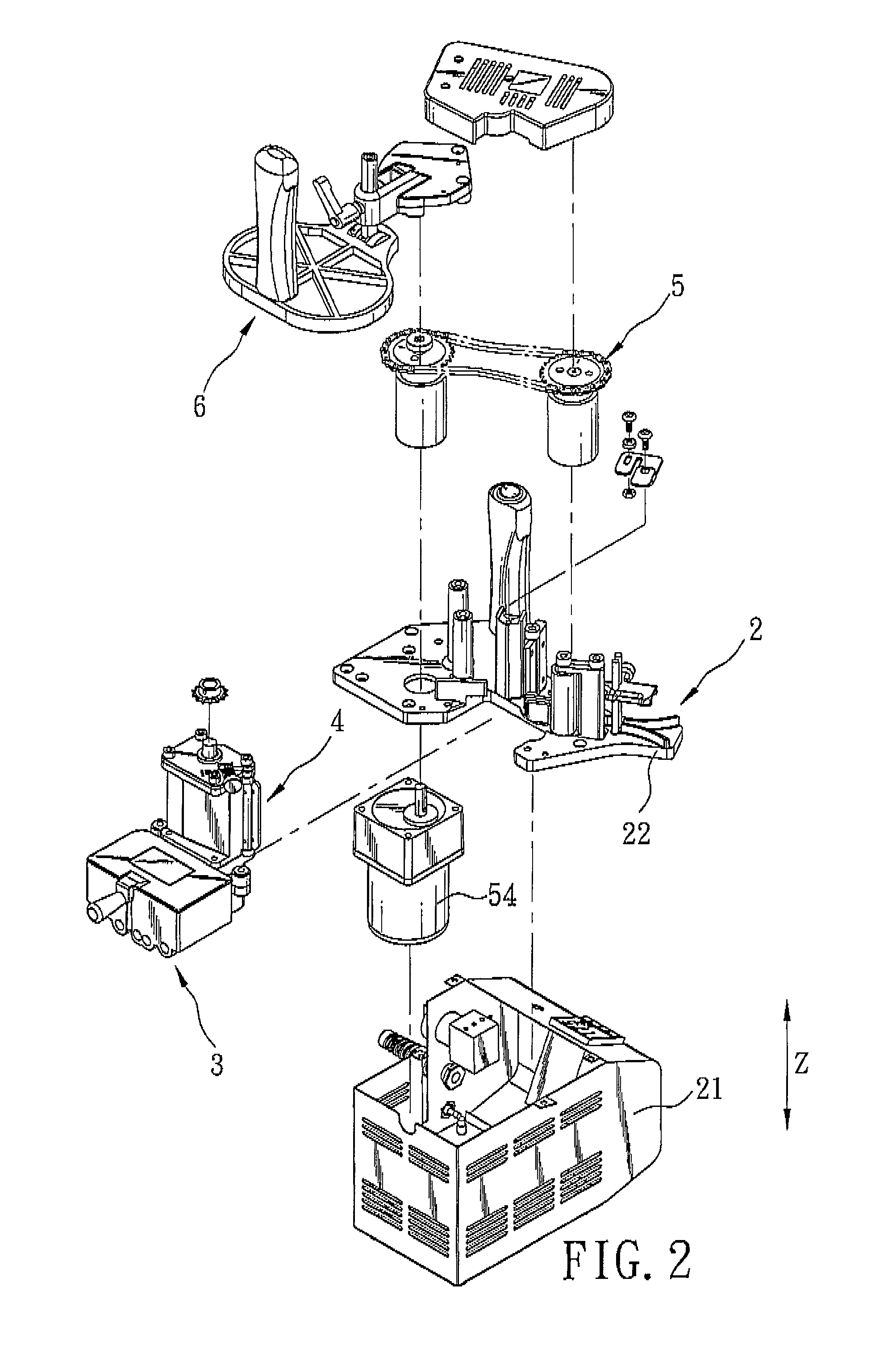
[0023]Referring to FIGS. 1 to 3, the preferred embodiment of an edge banding machine according to this invention is shown to have a machine body unit 2, a glue-applying unit 3, a glue-scratching unit 4, a transmission unit 5 and an adjustable grip unit 6.

[0024]Referring to FIGS. 2 to 4, the machine body unit 2 includes a machine housing 21 and a mounting plate 22 mounted fixedly on the machine housing 21.

[0025]Referring to FIGS. 5 to 7, the glue-applying unit 3 includes a glue container 31 mounted fixedly on the mounting plate 22, a supporting member 32 disposed fixedly and directly above the glue container 31, a cover 33 disposed fixedly on and above the supporting member 32, and a glue-applying roller 34 disposed pivotally on the cover 33, extending into the glue container 31, and rotatable relative to the glue container 31 and the supporting member 32 for applying glue over an edge band 100.

[0026]The glue container 31 has an accommodating space 35 permitting the glue-applying rol...


PUM


Abstract

An edge banding machine includes a machine body unit having a mounting plate, a glue-applying unit, a glue-scratching unit and a transmission unit. The glue-applying unit includes a glue container mounted fixedly on the mounting plate, a supporting member disposed fixedly and directly above the glue container and a glue-applying roller rotatably extending into the glue container. The glue-scratching unit includes a rotating shaft disposed rotatably on the supporting member, a glue-scratching plate disposed fixedly on the rotating shaft and extending toward the glue-applying roller, an adjustment rod disposed adjustably on the cover, and a connecting member connected between the adjustment rod and the rotating shaft such that movement of the adjustment rod results in rotation of the rotating shaft.

Description

BACKGROUND OF THE INVENTION[0001]1. Field of the Invention[0002]The invention relates to an edge banding machine, more particularly to an edge banding machine that can adjust the thickness of glue applied to an edge band.[0003]2. Description of the Related Art[0004]At present, there is a typical edge banding machine, as disclosed in International Patent Publication Number WO2006076871, that includes a glue-applying unit and a transmission unit. The glue-applying unit has a glue container and a glue-applying roller that is rotatable relative to the glue container. The transmission unit has a front conveying wheel and a rear conveying wheel that are disposed respectively at two sides of the glue-applying roller, and a belt that is connected between the front conveying wheel and the rear conveying wheel for driving the glue-applying roller.[0005]In use, an edge band is moved by the front conveying wheel to pass through the glue-scratching unit, so that it is moved by the front conveyin...

Claims


Application Information

Patent Timeline
IPC IPC(8): B05C1/00B05C11/11B05C13/00B05C11/00
CPCB27D5/003B05C11/041B05C1/0826B27G11/00
Inventor LIN, CHIN-CHI
Owner LIN CHIN CHI
Why Eureka
Try Eureka