
Microfluidic Device

a microfluidic device and microfluidic technology, applied in the direction of diaphragm valves, laboratory glassware, engine diaphragms, etc., can solve the problems of overwhelming chemical analysis and related devices, the need for technicians, and the current technique of burst valves

Inactive Publication Date: 2012-09-27
AMPOC FAR EAST CO LTD
View PDF0 Cites 12 Cited by
  • Summary
  • Abstract
  • Description
  • Claims
  • Application Information

AI Technical Summary

Benefits of technology

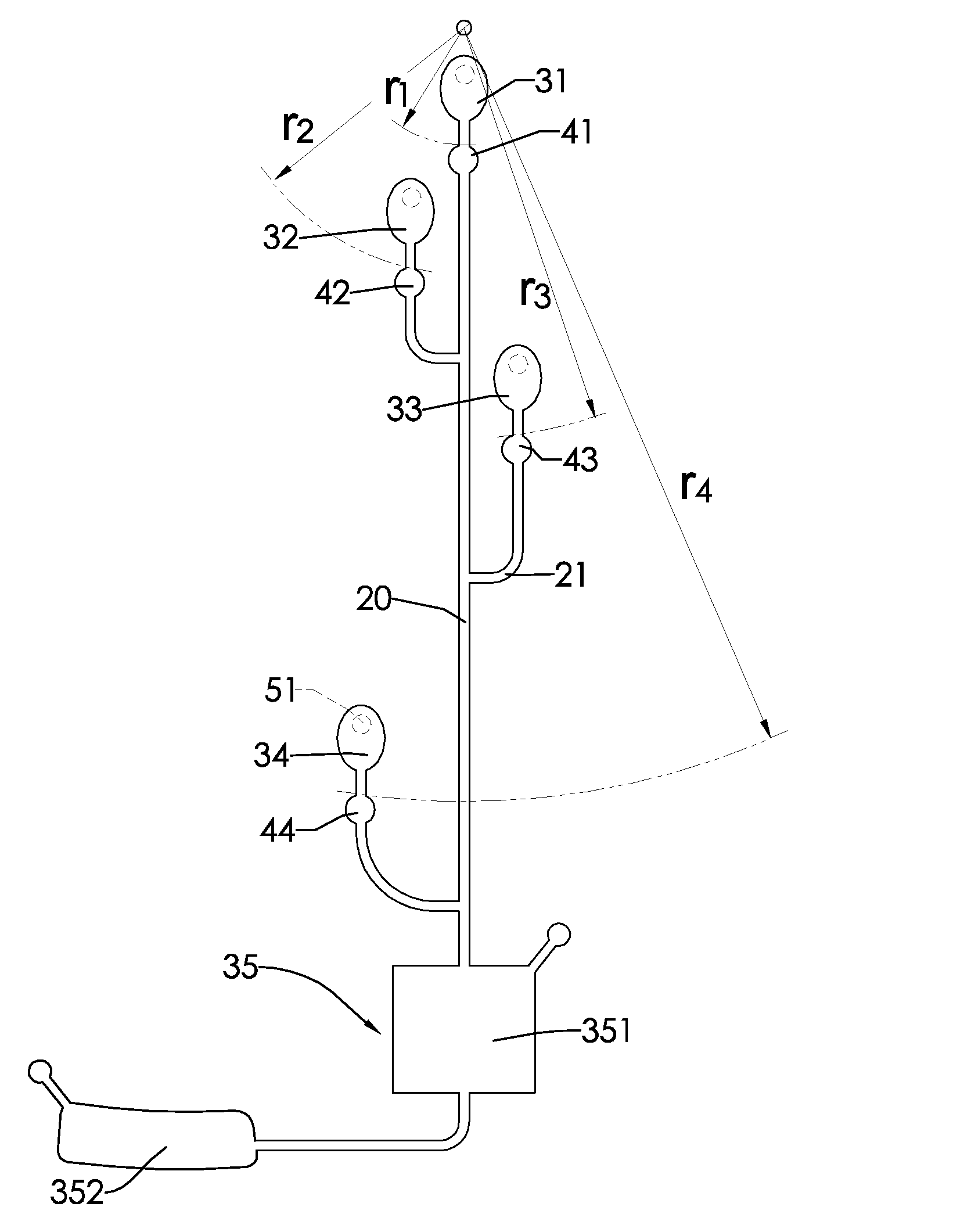
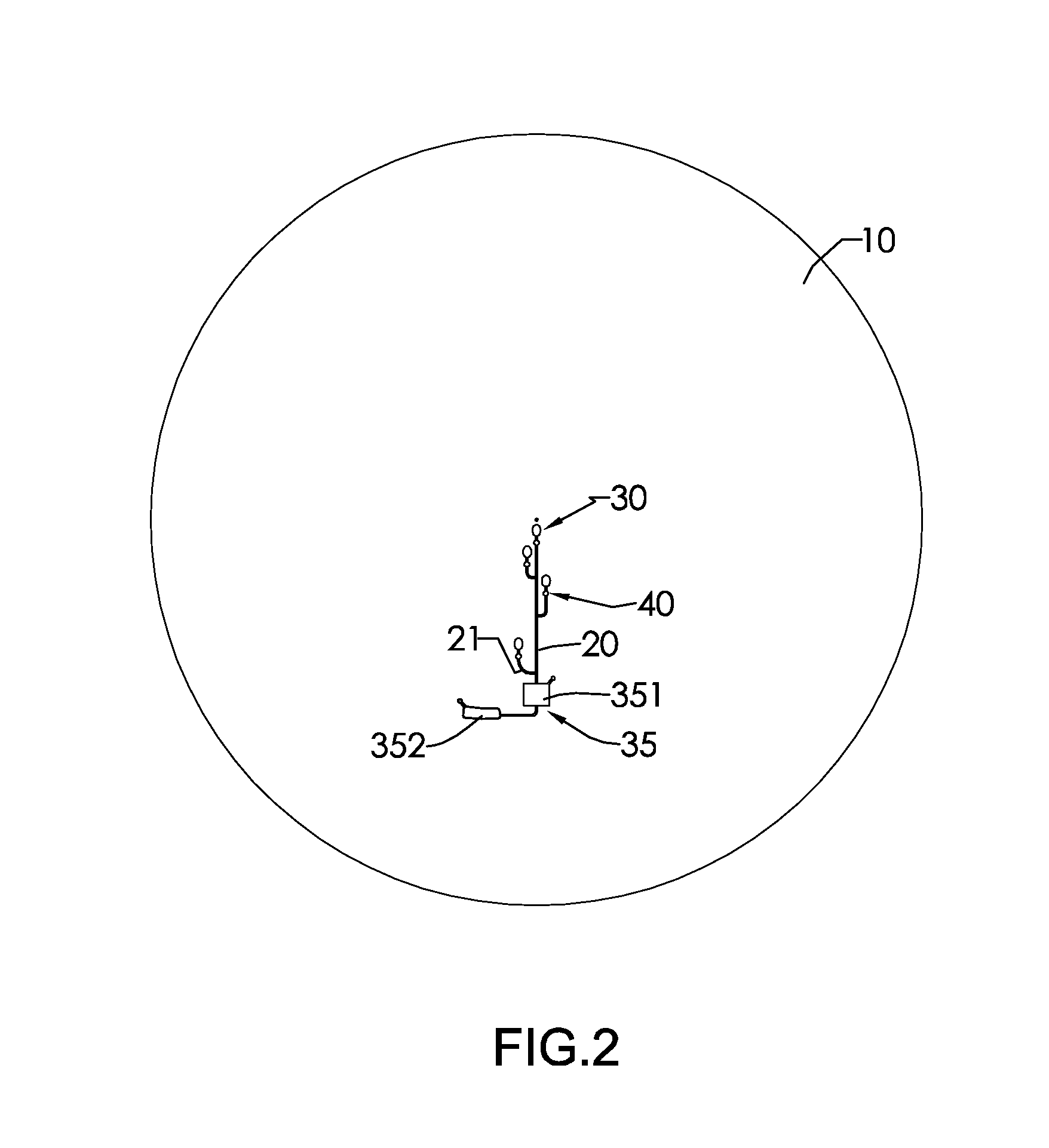
[0012]The body is in a shape of annular disk and has a top, a center and a circumference. The reservoirs are formed on the top of the body. Each channel is formed on the top of the body and connects to a corresponding reservoir. The channels include a main channel and at least one branch channel. The main channel is formed on the top of the body and extends in a direction from the center to the circumference of the body. Each capillary valve is mounted on a corresponding channel and at a distance substantially close to the center of the body so as to increase differences between the burst frequencies of the capillary valves. The cover is mounted on the top of the body and has multiple apertures corresponding to the reservoirs.
[0024]Based on the aforesaid descriptions, the radial distances of the capillary valves in accordance with the present invention are smaller than 4 cm. As compared to the conventional microfluidic techniques, the capillary valves are closer to the center of the body. The microfluidic device in accordance with the present invention can be beneficial in sequentially releasing fluid. By adjusting the valve width, orientation and surface modification of the capillary valves, the excellent effect of sequential releasing of fluid of the microfluidic device according to the present invention is useful for various applications on chemical analytical processes.

Problems solved by technology

Due to developments in medicine, pharmacy, biotechnology and environmental monitoring, overwhelming chemical analysis and related devices and technicians are required.
Moreover, μTAS requires smaller amounts of samples or reagents, resulting in decrease of expenses on reagents.
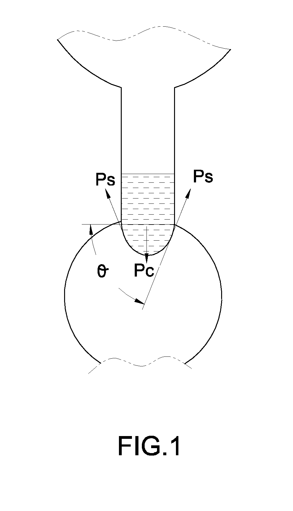
Therefore, current techniques of burst valves have disadvantages of unable to effectively release fluid in correct sequence.

Method used


Image

  • Microfluidic Device
  • Microfluidic Device
  • Microfluidic Device

Examples


examples

[0048]1. Evaluating Relationship Between Radial Distance and Burst Frequency of a Capillary Valve:

[0049]One of the capillary valves 40 is formed at a radial distance of 0.5 cm and others are formed at an interval of 0.4 cm on the body 10. A valve width of each capillary valve 40 is 200 μm. The burst frequency of each capillary valve is determined. The relationship between radial distance and burst frequency of the capillary valve is shown in FIG. 5. Within a range of shorter radial distance between 0 and 1.5 cm, burst frequency of each capillary valve 40 drastically differs with radial distance. While within a range of larger radial distance between 2.0 and 4.5 cm, burst frequencies of capillary valves 40 differ little from each other and even overlap.

[0050]2. Comparing Burst Frequencies of Capillary Valves with Different Radial Distances:

[0051]Table 1 shows the radial distances and the valve widths of the first capillary valve 41, the second capillary valve 42, the third capillary ...


PUM


Abstract

A microfluidic device has a body, multiple channels, multiple reservoirs and multiple capillary valves. The reservoirs are formed on the body. Each channel is formed on the body and connects to a corresponding reservoir. The channels include a main channel and at least one branch channel. The main channel is formed on the top of the body and extends in a direction from the center to a circumference of the body. Each capillary valve is mounted on a corresponding channel and at a distance substantially close to the center of the body so differences between the burst frequencies of the capillary valves are increased. The microfluidic device has an excellent flow control on sequentially releasing fluid through distinct burst frequencies of microcapillary valves.

Description

BACKGROUND OF THE INVENTION[0001]1. Field of the Invention[0002]The present invention relates to a microfluidic device, and more particularly to a microfluidic device motivated by centrifugal force that has an improved flow control of fluid on its flowing into channels by adjusting burst frequencies of capillary valves.[0003]2. Description of the Prior Arts[0004]Due to developments in medicine, pharmacy, biotechnology and environmental monitoring, overwhelming chemical analysis and related devices and technicians are required. However, the general public needs a more convenient and simpler analytical process without being limited by technical knowledge, devices and occasions.[0005]With progresses of microelectronic techniques and semiconductors, great efforts have been devoted to the development of efficient, sensitive, precise and miniature automatic detection techniques in the field of biological analysis and biomedical diagnostics. The concept of Micro Total Analysis Systems (μTA...

Claims


Application Information

Patent Timeline
IPC IPC(8): F15D1/00
CPCB01L3/502738B01L2200/0621B01L2400/084B01L2400/0409B01L2400/0688B01L2300/0803Y10T137/877
Inventor SHIH, CHIH-HSINWU, HOU-JINYEN, CHIH-HUONGCHEN, WEN-HAOFAN, KANG YANGHUNG, JIN PIN
Owner AMPOC FAR EAST CO LTD
Learn More