Device and method for transporting elongate objects using pick-up truck

a technology of elongated objects and pickup trucks, which is applied in the direction of transportation and packaging, metal working apparatus, manufacturing tools, etc., can solve the problems of long mounting process, increased risk of shifting in transport and even leaving the vehicle, and dangerous situations, etc., and achieves small and portable effect and convenient storag

Inactive Publication Date: 2012-09-27
MOORE KEVIN
View PDF6 Cites 4 Cited by
  • Summary
  • Abstract
  • Description
  • Claims
  • Application Information

AI Technical Summary

Benefits of technology

[0011]It is another object of the present invention to provide a device and method for the transport of lengthy objects on a pick-up truck that securely holds the transported object and limits unwanted lateral movement of the transported object.
[0012]It is a further object of the pre...

Problems solved by technology

However, when objects exceed these certain dimensions, they are more likely to shift in transport and even leave the vehicle.
Indeed, anyone who has traveled on the highways of an urban area has seen where improperly secured objects, such as ladders, boards and the like, have fallen out of a transporting vehicle and partially, or completely, obstruct the roadway.
These are very dangerous situations.
H...

Method used


Image

  • Device and method for transporting elongate objects using pick-up truck
  • Device and method for transporting elongate objects using pick-up truck
  • Device and method for transporting elongate objects using pick-up truck

Examples


first embodiment

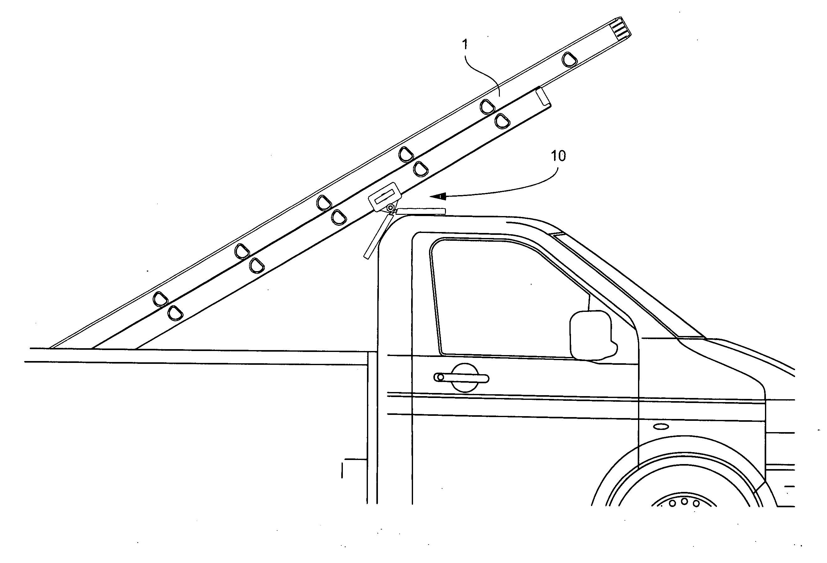
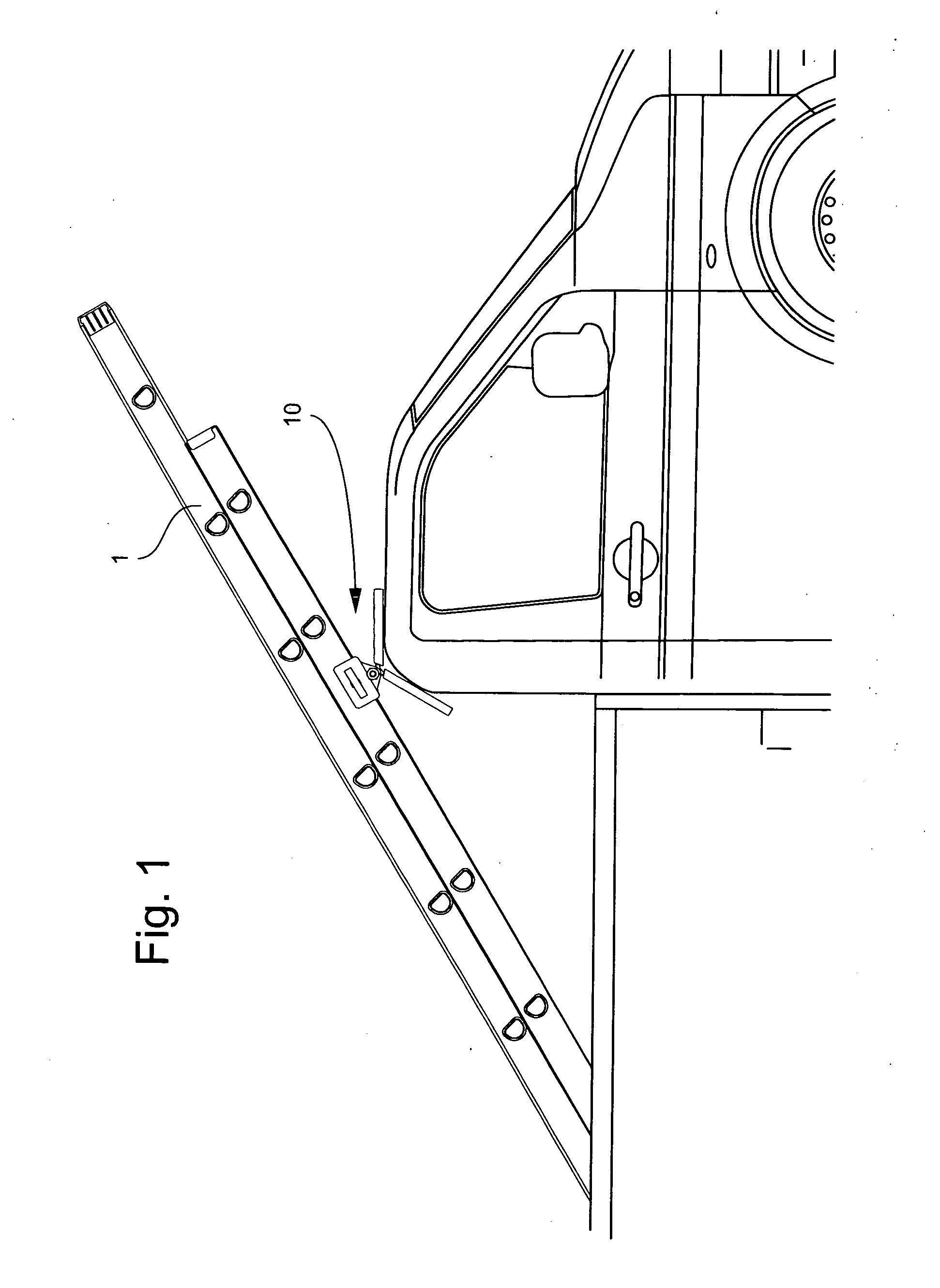
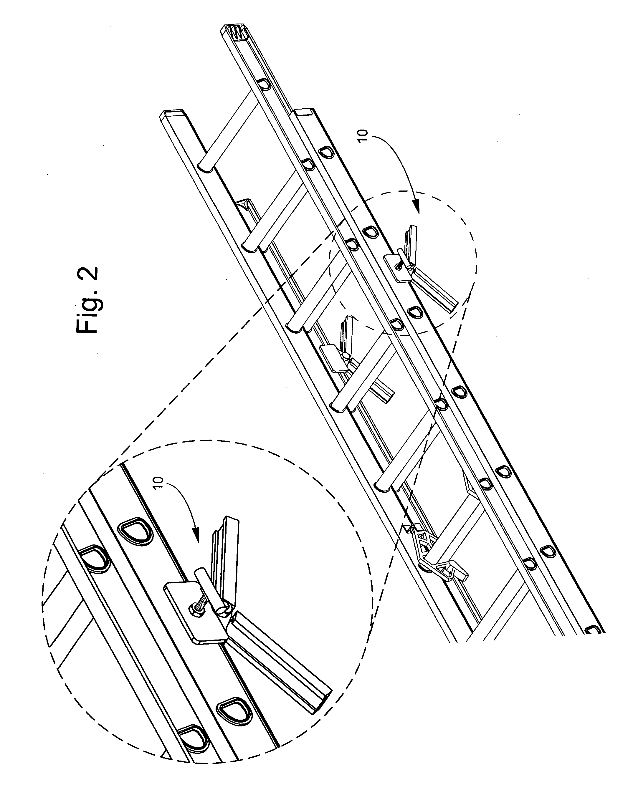
[0028]In a first embodiment, illustrated in FIGS. 1-5, each unit 10 comprises a generally U shaped body 20 with a base plate 21 and first and second generally parallel side plates, 22 and 23, respectively, attached to the base plate 21. In a preferred embodiment, there is a threaded aperture 24 located in a generally central position in the first side plate 22. The body 20 further has at least one, preferably two pivot tangs 25 that are attached to an under side of the base plate 21. Each pivot tang 25 includes a centrally located pivot tang aperture 26. In a preferred embodiment, there is a small channel 27 cut into the vertex of the base plate 21 and the second side 23. This channel 27 is sized to fit a projecting portion a leg of a ladder 1 (see FIG. 4).

[0029]Each unit 10 further includes a pivotable arm 30. Each pivotable arm 30 has an arm body 31 that includes a pivot arm aperture 32 and at least one, preferably two, arms 33. In a preferred embodiment, the included angle betwee...

second embodiment

[0033]In a second embodiment, illustrated in FIGS. 6-8, each unit 10 comprises a unit body 50 having a pivot aperture 51. Pivotally attached to the unit body 50 are at least one, preferably two unit arms 52. Each unit arm 52 is further provided with a cushion 53.

[0034]In a preferred version of the second embodiment the unit arms 52 are attached to the unit body 50 by a spacing segment, or arm body, 54. It is understood that the unit body 50 may be sized and shaped large enough to dispose of the spacing segment 54 or the spacing segment 54 may be an integral part of the unit body 50 and still fall within the scope of the present invention.

[0035]In the preferred version of the second embodiment, each kit also includes an axle rod 56, two hub elements 57, and two securing mechanisms, such nuts 58.

[0036]In use the axle rod 56 is inserted through the barrel of a ladder step, the each hub element 57 is threaded onto the axle rod 56, one at each end of the axle rod 56, leaving a portion of...

third embodiment

[0037]In a third embodiment, illustrated in FIGS. 9-11, each unit 10 comprises a unit body 60 having a pivot aperture 61. Attached to the unit body 60 are at least one, preferably two unit arms 62. Each unit arm 62 is further provided with a cushion 63.

[0038]In a preferred version of the third embodiment the unit arms 62 are attached to the unit body 60 by a spacing segment 64. It is understood that the unit body 60 may be sized and shaped large enough to dispose of the spacing segment 64 or the spacing segment 64 may be an integral part of the unit body 60 and still fall within the scope of the present invention. Further, the preferred version of the third embodiment includes a curved pivot guard 65 coaxial with the pivot aperture 61 and laterally spaced away from the pivot aperture 61.

[0039]In the preferred version of the third embodiment each kit also includes a pivot insert 66 and pivot pin or pivot bolt 67 for each unit body 60. Preferably the pivot insert 66 is a threaded inse...


PUM

PropertyMeasurementUnit
Angleaaaaaaaaaa

Abstract

A kit for securing ladders to a vehicle comprising at least two units, each unit comprising a body with a pivotally attached arm unit, wherein each unit is adapted to be secured to a portion of a ladder. Each arm unit comprises an arm body, with a pivot aperture, and two attached arms. The included angle between the two attached arms is 120°. A method for securing ladders to a vehicle comprising the steps of: providing two units, each unit comprising a body with a pivotally attached arm unit; attaching the two units to opposite sides of a ladder; placing the ladder in the bed of a pick-up such that the pivotally attached arm units are in contact with the cab of the pick-up; and securing the ladder to the pick-up to prevent unwanted movement.

Description

FIELD OF THE INVENTION[0001]The present invention relates generally to a device and method used in loading and transporting lengthy objects on a pick-up truck. More specifically, the present invention is a device and method for securing the lengthy objects to the pick-up truck such that they do not easily shift during transportation.BACKGROUND[0002]Pick-up trucks are designed to safely transport objects of certain dimensions. However, when objects exceed these certain dimensions, they are more likely to shift in transport and even leave the vehicle. This usually occurs when the object is lengthy and has been propped against either the cab or the tailgate of the pickup truck. Examples are found in the transport of ladders, long boards, poles, and other lengthy objects.[0003]Indeed, anyone who has traveled on the highways of an urban area has seen where improperly secured objects, such as ladders, boards and the like, have fallen out of a transporting vehicle and partially, or complet...

Claims


Application Information

Patent Timeline
IPC IPC(8): B60R9/04B23P19/04
CPCY10T29/49826B60R9/0485
Inventor MOORE, KEVIN
Owner MOORE KEVIN
Why Eureka
Try Eureka