Antenna module

a technology of antenna module and impedance bandwidth, applied in the direction of antenna details, simultaneous aerial operations, antennas, etc., can solve the problems of poor impedance matching effect of conventional design and inability to meet the increasing bandwidth requirement, so as to reduce imaginary parts of impedance and increase impedance bandwidth

Active Publication Date: 2012-09-27
WISTRON CORP
View PDF9 Cites 146 Cited by
  • Summary
  • Abstract
  • Description
  • Claims
  • Application Information

AI Technical Summary

Benefits of technology

[0007]In the embodiments of the invention, a short path is built by the short conductor which is separated from the radiator. A capacitance effect is formed between the short conductor and the radiator (equivalent capacitance in series with the radiator), and an inductance effect is formed between the short conductor and the ground element (equivalent inductance in parallel connected with the ground element) to reduce imaginary parts of impedance and to increase impedance bandwidth. The transmission bands of the antenna modules of the embodiments of the invention conform to the GSM850 / 900 / DCS / PCS, UMTS BAND 1 / BAND 2 / BAND 5 / BAND 8,802.11 a / b / g standards.

Problems solved by technology

However, conventional design has poor impedance matching effect, and cannot satisfy increasing requirement of bandwidths.

Method used


Image

  • Antenna module
  • Antenna module
  • Antenna module

Examples


first embodiment

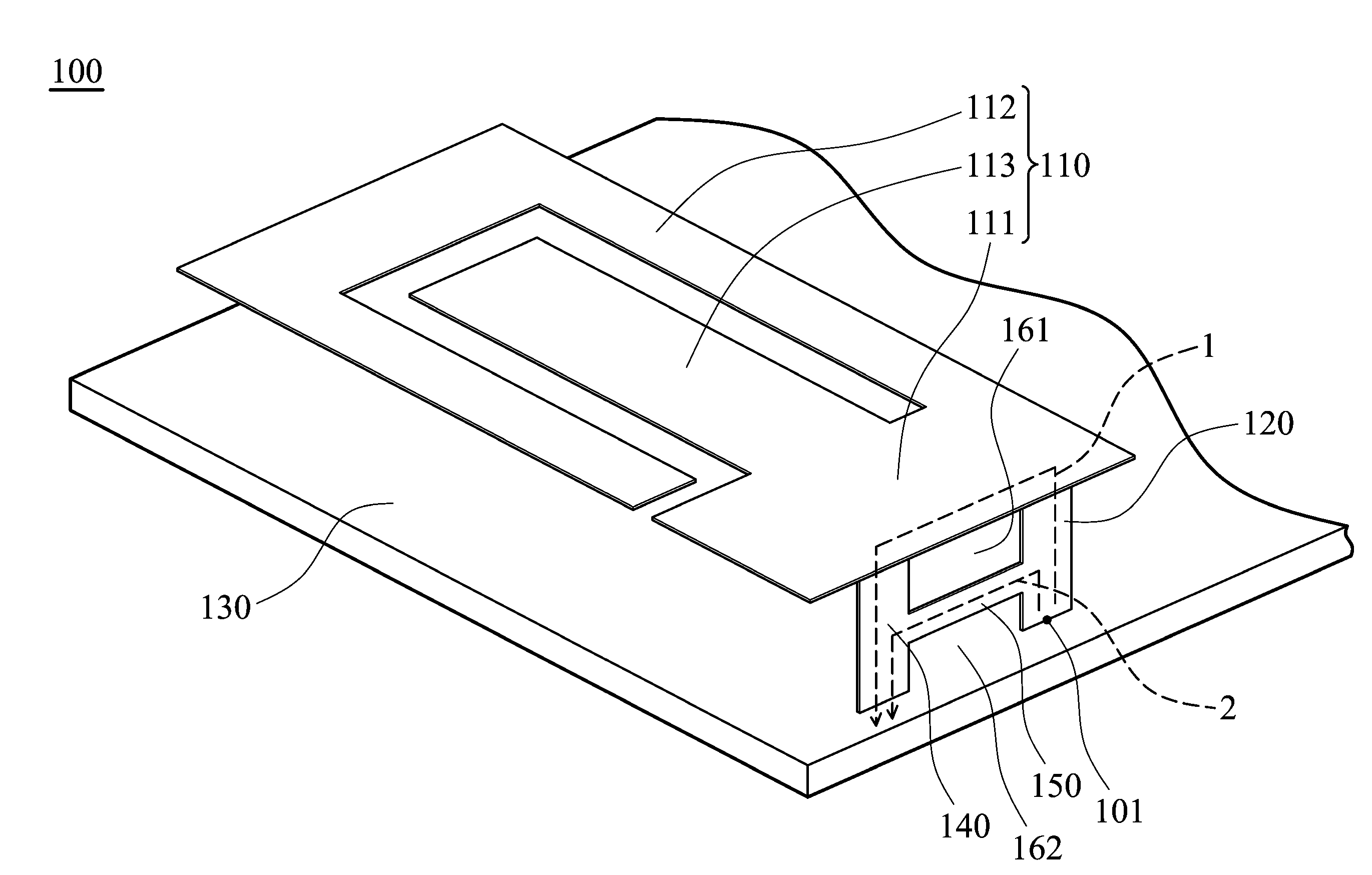
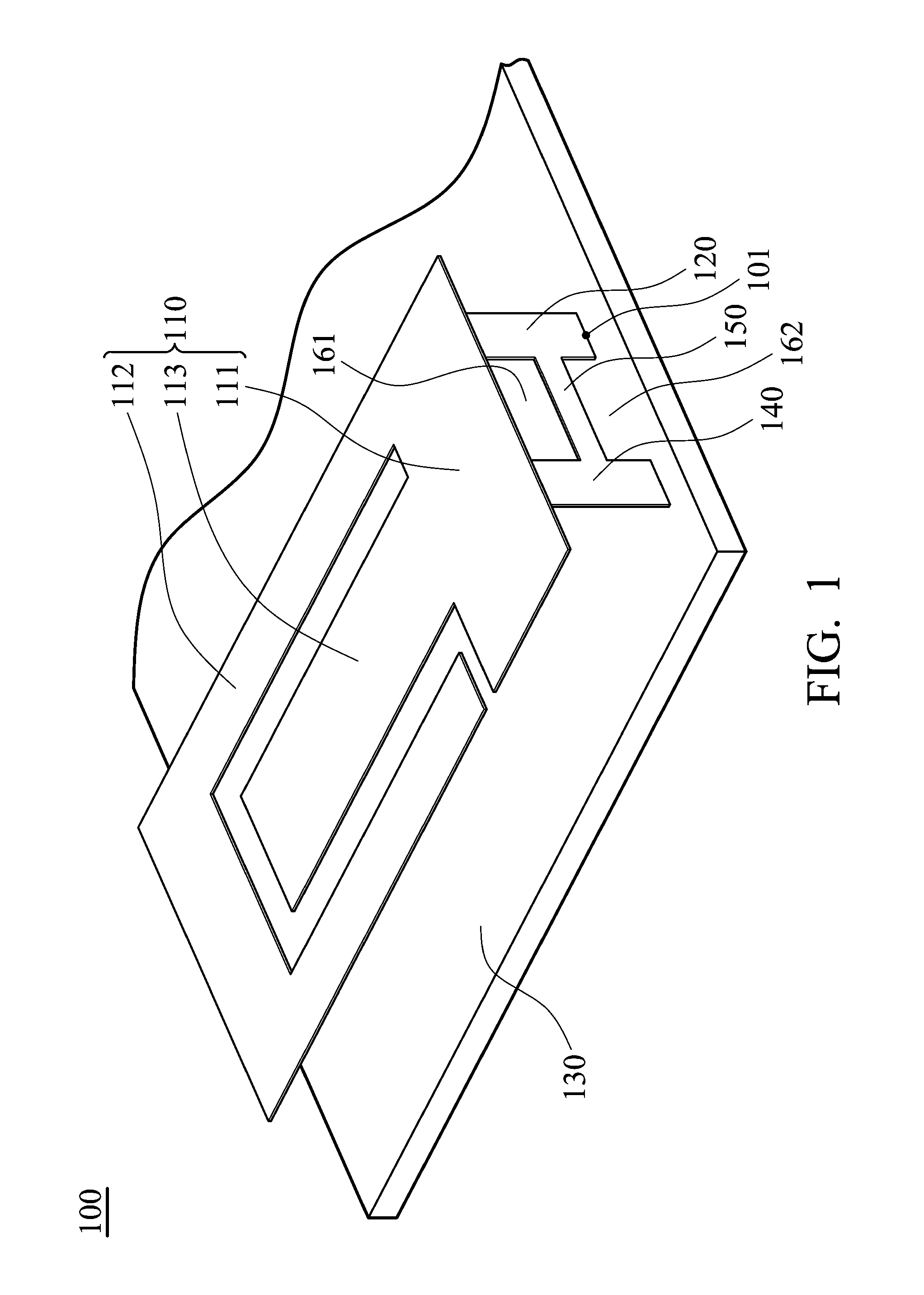
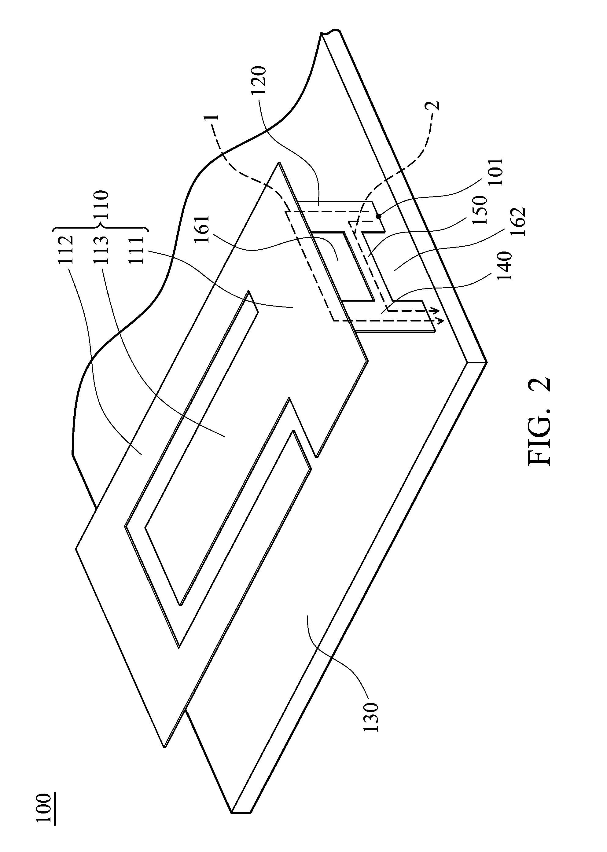
[0018]FIG. 1 shows an antenna module 100 of the invention, including a radiator 110, a feed conductor 120, a ground element 130, a ground conductor 140 and a short conductor 150. The feed conductor 120 is connected to the radiator 110. The ground conductor 140 connects to the radiator 110 and the ground element 130. The short conductor 150 connects to the feed conductor 120 and the ground conductor 140. The feed conductor 120 is separated from the ground element 130. A signal is fed to the feed conductor 120 via a feed point 101.

[0019]In this embodiment, the ground conductor 140 is parallel to the feed conductor 120. The radiator 110 is parallel to the ground element 130. The short conductor 150 is respectively perpendicular to the ground conductor 140 and the feed conductor 120.

[0020]The radiator 110 includes a first section 111, a second section 112 and a third section 113. The second section 112 is connected to the first section 111. The third section 113 is connected to the firs...

second embodiment

[0025]FIG. 5 shows an antenna module 200 of the invention, wherein the shape of the third section 112′ is modified, and the second section 112′ does not surround the third section 113′. In the invention, the shape of the radiator can be modified, and the radiators disclosed in the embodiments do not restrict the invention.

[0026]FIG. 6 shows an antenna module 300 of a third embodiment of the invention, and FIG. 7 shows an antenna module 400 of a fourth embodiment of the invention. The antenna module 300 of the third embodiment differs from the first embodiment in the design of the radiator 310. The antenna module 400 of the fourth embodiment differs from the first embodiment in the design of the radiator 410.

[0027]In one embodiment, the length of the short conductor can be quarter of wavelength of a low band signal, and the impedance bandwidth for low frequency bands can therefore be further increased. The short conductor can be taken as an impedance matching circuit, which provides ...


PUM


Abstract

An antenna module is provided. The antenna module includes a radiator, a feed conductor, a ground element, a ground conductor and a short conductor. The feed conductor is connected to the radiator. The ground conductor connects the radiator to the ground element. The short conductor connects the feed conductor to the ground conductor.

Description

CROSS REFERENCE TO RELATED APPLICATIONS[0001]This Application claims priority of Taiwan Patent Application No. 100110322, filed on Mar. 25, 2011, the entirety of which is incorporated by reference herein.BACKGROUND OF THE INVENTION[0002]1. Field of the Invention[0003]The present invention relates to an antenna module, and in particular relates to an antenna module with increased impedance bandwidth.[0004]2. Description of the Related Art[0005]Conventional planar inverted F antennas include a feed conductor, a radiator, a ground element and a short element. The radiator is connected to the feed conductor. The short element connects to the radiator and the ground element. Conventionally, the short element grounds an end of the radiator to improve impedance matching. However, conventional design has poor impedance matching effect, and cannot satisfy increasing requirement of bandwidths.BRIEF SUMMARY OF THE INVENTION[0006]An antenna module is provided, includes a radiator, a feed conduc...

Claims


Application Information

Patent Timeline
Patent Type & Authority Applications(United States)
IPC IPC(8): H01Q9/04H01Q5/364
CPCH01Q1/243H01Q5/364H01Q9/0421
Inventor HU, PEI-CHENGSU, KUO-CHANGTSAI, WEN-YI
Owner WISTRON CORP
Why Eureka
Try Eureka