

Liquid ejecting apparatus
- Summary
- Abstract
- Description
- Claims
- Application Information
AI Technical Summary
Benefits of technology
Problems solved by technology
Method used
Image

Examples
embodiment
Example of Configuration of Printer 1
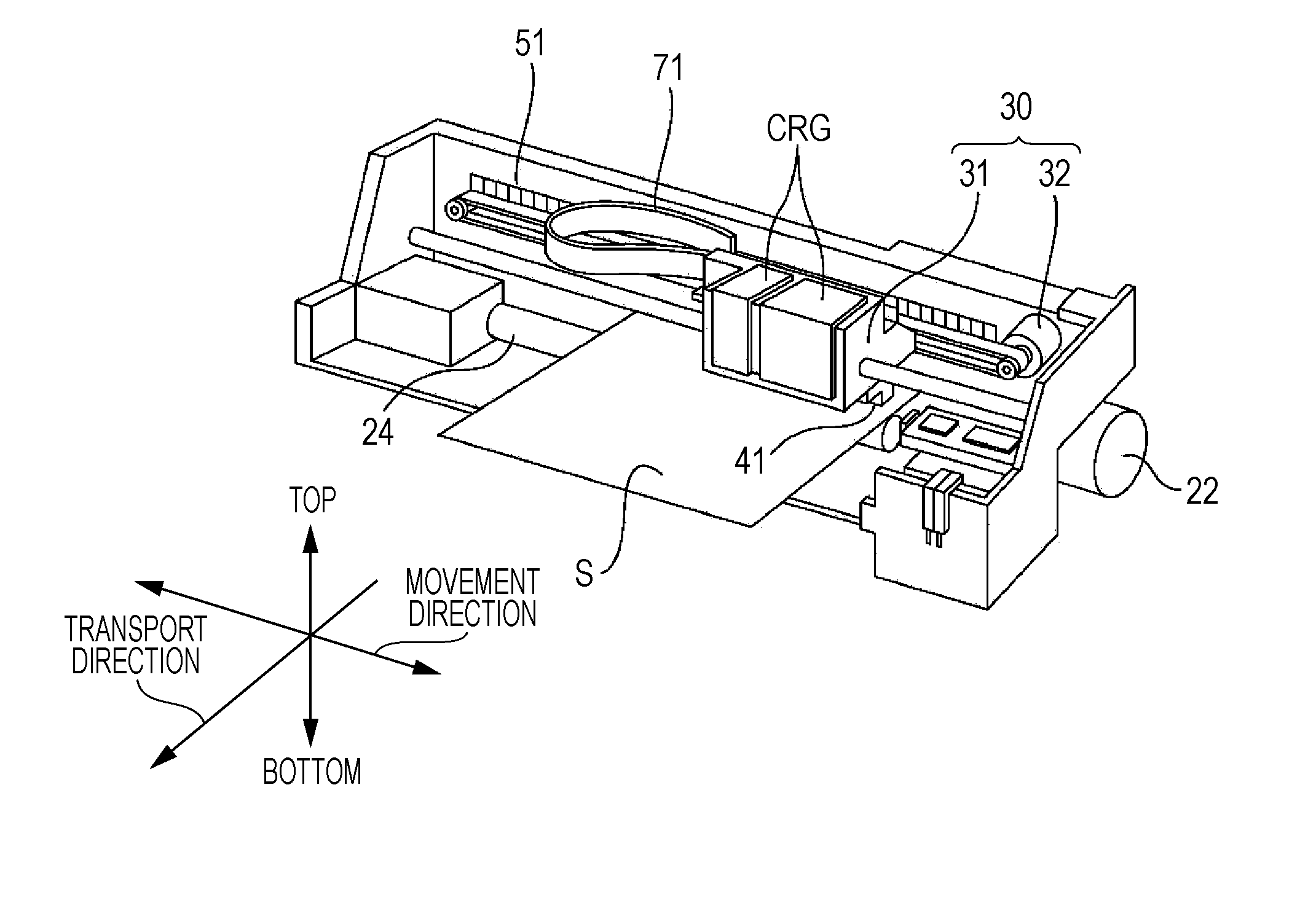
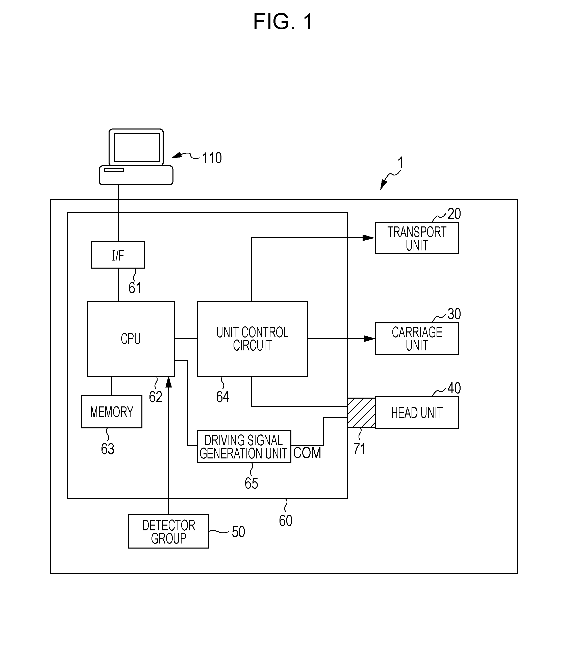
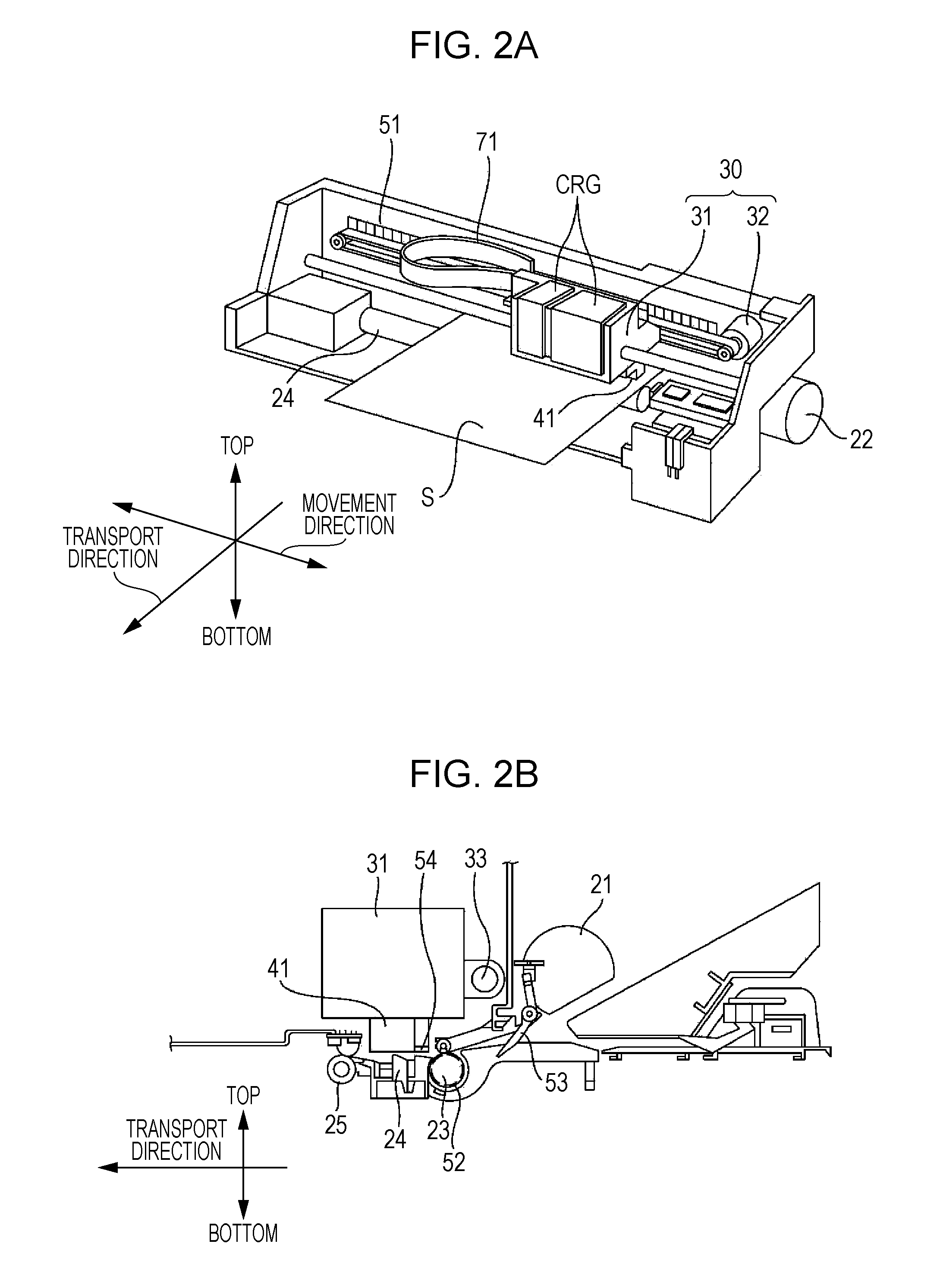
[0032]An example of the configuration of the printer 1 will be described using FIGS. 1 through 2B. FIG. 1 is a block diagram illustrating the overall configuration of the printer 1 according to this embodiment. FIG. 2A is a perspective view of the printer 1, whereas FIG. 2B is a cross-sectional view of the printer 1 seen from the side.
[0033]The printer 1 according to this embodiment includes: a transport unit 20 serving as an example of a transport unit; a carriage unit 30; a head unit 40 serving as an example of a head unit; a detector group 50; and a controller 60. Having received print data from a computer 110, which is an external device, the printer 1 controls the various units (the transport unit 20, the carriage unit 30, and the head unit 40) using the controller 60. The controller 60 prints an image onto paper by controlling the various units based on the print data received from the computer 110. The internal state of the printer 1 is mo...
first working example
[0070]First, the head case 45 according to the first working example will be described using FIG. 6.
[0071]Note that an ink introduction pin, an ink flow channel, and so on to which the ink cartridge CRG is mounted are not depicted in the head unit 40 shown in FIG. 6. Furthermore, although the head case 45 in FIG. 6 is illustrated as having its top surface open, it is assumed that this top surface is sealed.
[0072]The head case 45 is a casing that is supported by the carriage 31 and that is configured so as to be capable of housing the head 41 and the head control unit HC.
[0073]The head case 45 is formed primarily of a synthetic resin, but has a section 46 that is formed of a metal member (this will be called a “metal section 46” hereinafter). In other words, the head case 45 is formed so that a synthetic resin and the metal member are integrated. Furthermore, the head case 45 has the nozzle plate 42 on its bottom surface.
[0074]The reservoir plate 43 is affixed to the upper surface of...
second working example
[0086]Next, the head case 45 according to the second working example will be described using FIG. 7.
[0087]Note that, as in FIG. 6, an ink introduction pin, an ink flow channel, and so on to which the ink cartridge CRG is mounted are not depicted in the head unit 40 shown in FIG. 7. Furthermore, although the head case 45 in FIG. 7 is illustrated as having its top surface open, it is assumed that this top surface is sealed.
[0088]With the head case 45 according to the second working example, the configuration of the metal section 46 is different from that in the head case 45 according to the first working example. Accordingly, the metal section 46 that has a different configuration from that in the first working example will be described.
[0089]The head case 45 according to the second working example has, as shown in FIG. 7, a plurality of rectangular fins 46a in the metal section 46.
[0090]The plurality of fins 46a, which protrude downward, are formed as an integral part of the metal se...
PUM
 Abstract
Description
Claims
Application Information