Liquid cooling system

Inactive Publication Date: 2006-05-23
FORWARD ELECTRONICS CO LTD
View PDF4 Cites 5 Cited by
  • Summary
  • Abstract
  • Description
  • Claims
  • Application Information

AI Technical Summary

Benefits of technology

[0013]As indicated above, the electric fan is set in between the first cooler module and the second cooler module to suck air into one of the first cooler module and the second cooler module and to blow air into the other of the first cooler module and the second cooler module, thereby dissipating heat from the first coiled tube of

Problems solved by technology

Further, because the first cooler module 91 has a coiled tube 911 installed therein and the second cooler module 92 has a coiled tube 921 installed th

Method used


Image

  • Liquid cooling system
  • Liquid cooling system
  • Liquid cooling system

Examples


Example

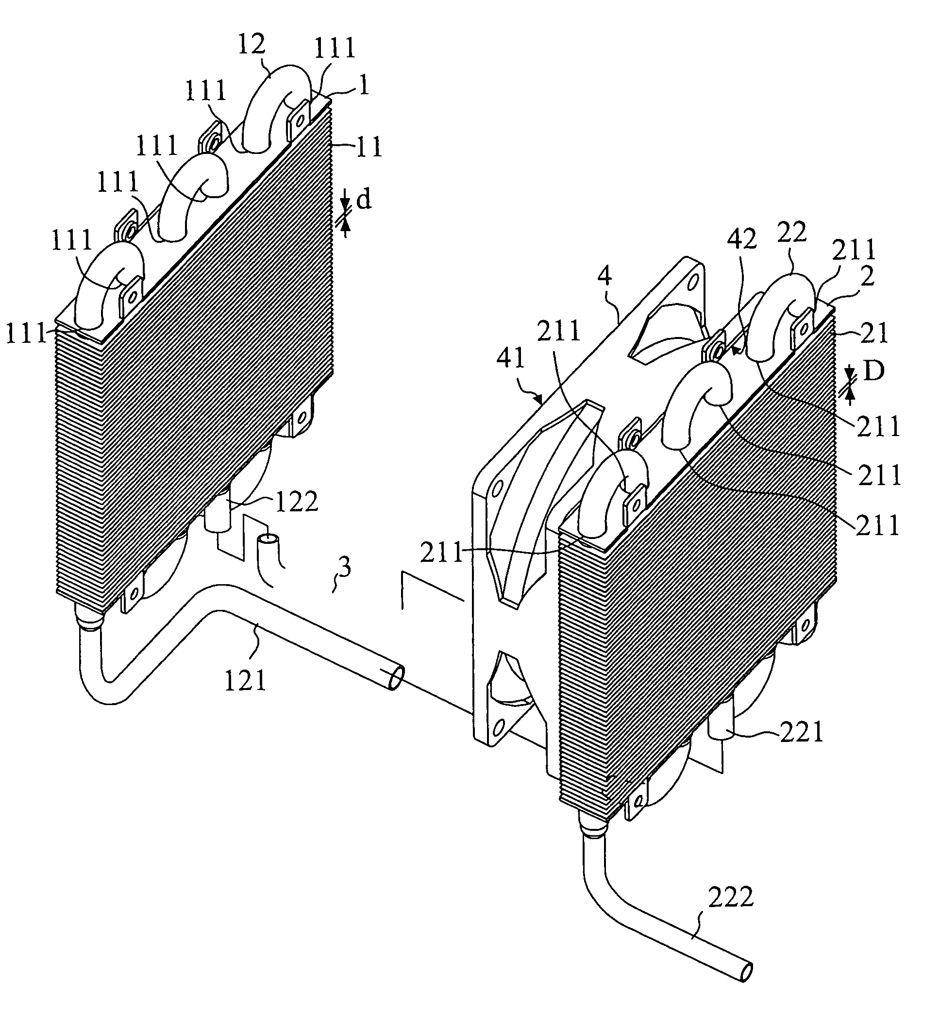
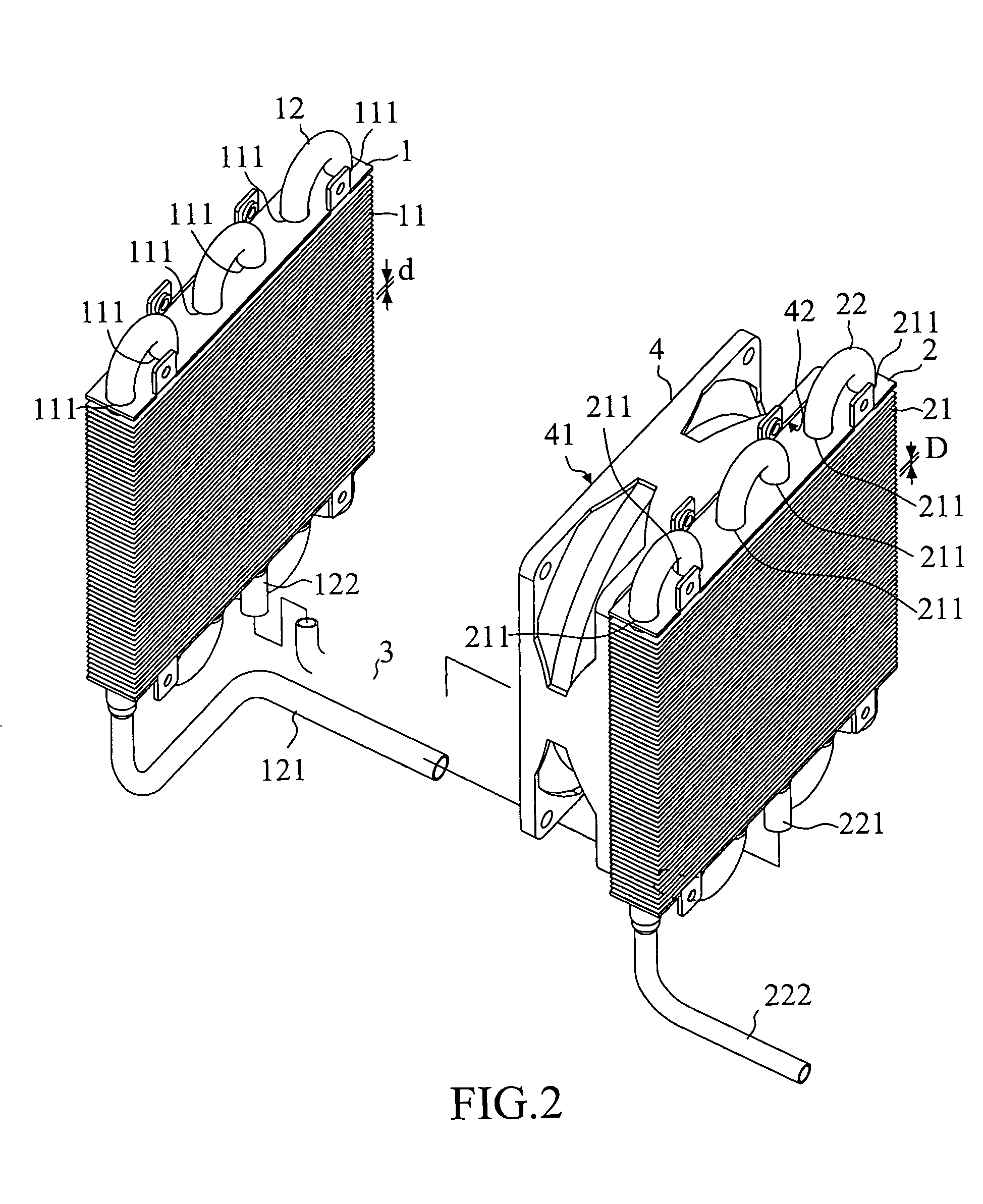
[0019]Referring to FIG. 2 and FIG. 3, a liquid cooling system in accordance with the present invention is shown comprised of a first cooler module 1, a second cooler module 2, a connecting tube 3, and an electric fan 4.

[0020]The first cooler module 1 comprises a plurality of first radiation fins 11 and a first coiled tube 12. The first radiation fins 11 are transversely arranged in parallel at a predetermined pitch d, each having a plurality of vertically extending first through holes 111. The first coiled tube 12 is a continuously S-shaped tube vertically inserted through the vertically extending first through holes 111 of the first radiation fins 11, having a first inlet 121 and a first outlet 122.

[0021]The second cooler module 2 is arranged in parallel with the first cooler module 1 at one side, comprising a plurality of second radiation fins 21 and a second coiled tube 22. The second radiation fins 21 are transversely arranged in parallel at a predetermined pitch D, each having ...


PUM


Abstract

A liquid cooling system is disclosed to include a first cooler module, a second cooler module, a connecting tube connected between the vertically arranged coiled tube of the first cooler module and the vertically arranged coiled tube of the second cooler module, a working liquid passing through the coiled tubes of the two cooler modules, and an electric fan set in between the two cooler modules to suck air into the first cooler module and to blow air into the second cooler module, enhancing the heat dissipation effect.

Description

BACKGROUND OF THE INVENTION[0001]1. Field of the Invention[0002]The present invention to a cooling system and more particularly, to a liquid cooling system.[0003]2. Description of Related Art[0004]In regular electronic products, heat energy produced during operation must be effectively expelled, keeping normal working of the products.[0005]In a computer, the CPU is the main heat generating source. A CPU cooler may be used and attached to the CPU for dissipating heat from the CPU. This CPU cooler is comprised of a cooler module and an electric fan. The cooler module has cooling water flowing therein to carry heat energy by means of heat pipe theory, enabling heat energy to be dissipated into the outside open air by means of the suction or blowing action of the electric fan.[0006]FIG. 1 shows a liquid cooling system according to the prior art. According to this design, the liquid cooling system comprises a first cooler module 91 and a second cooler module 92 arranged in parallel, and ...

Claims


Application Information

Patent Timeline
IPC IPC(8): F25D17/06
CPCF28D1/0477F28F9/262H01L23/467H01L23/473F28D2021/0031H01L2924/0002H01L2924/00
Inventor HUANG, JUNG FONGHUANG, CHIH CHIEN
Owner FORWARD ELECTRONICS CO LTD
Why Eureka
Try Eureka