

Fixture, battery unit and battery module
- Summary
- Abstract
- Description
- Claims
- Application Information
AI Technical Summary
Benefits of technology
Problems solved by technology
Method used
Image

Examples
Embodiment Construction
[0075]Hereinafter a fixture, a battery unit and a battery module of the present disclosure will be described in detail in combination with the figures.
[0076]Firstly, a fixture according to a first aspect of the present disclosure will be described.
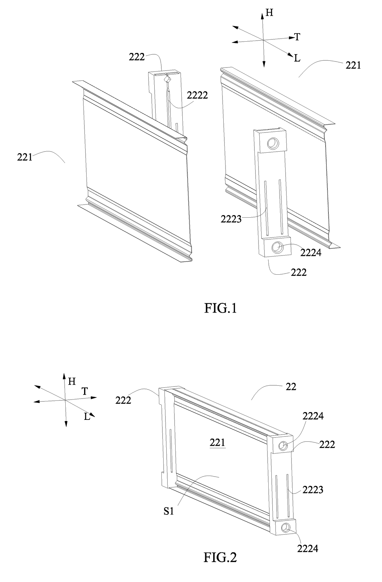
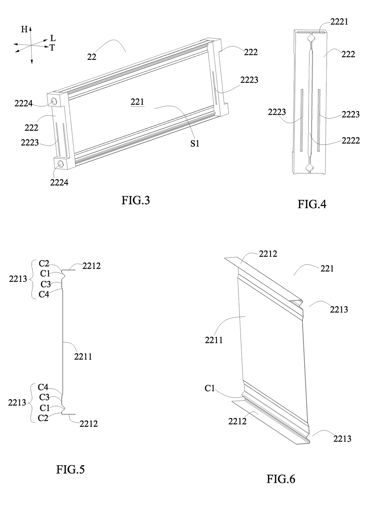
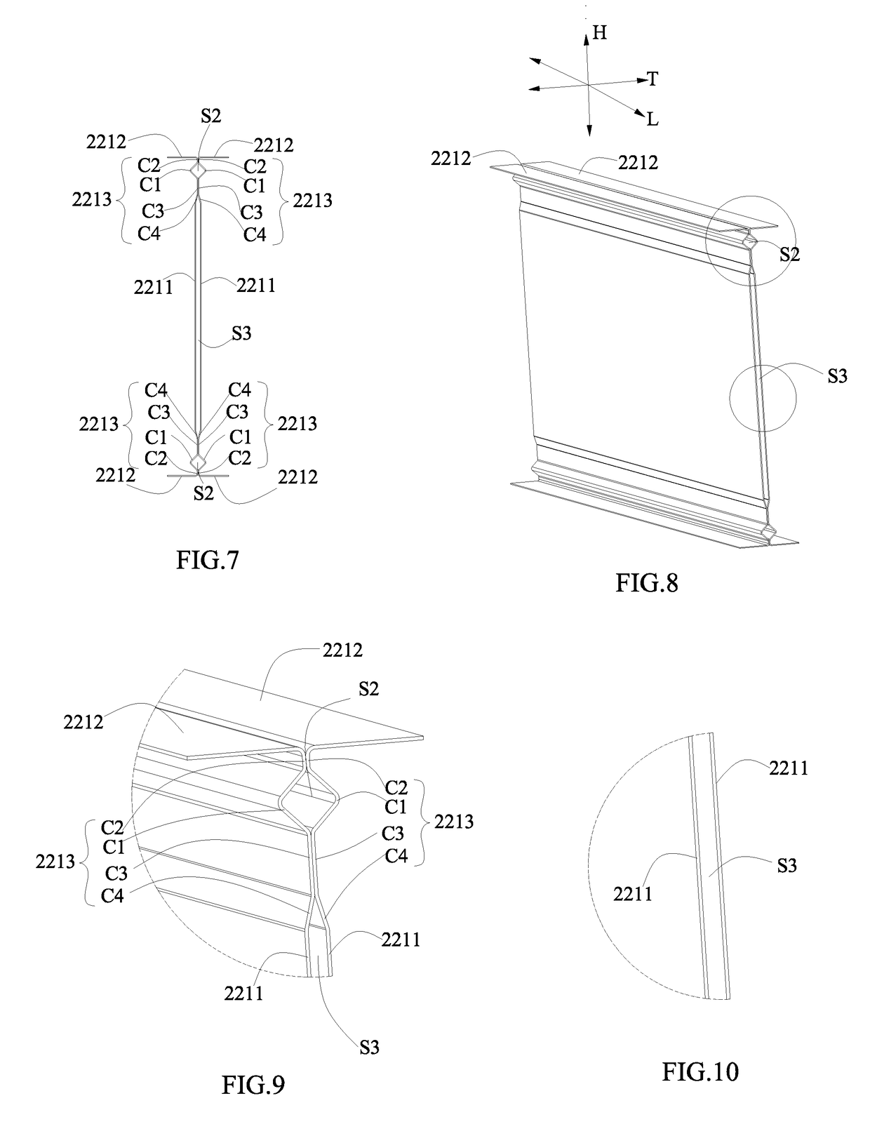
[0077]As shown in FIG. 1 to FIG. 10, a fixture 22 of the first aspect of the present disclosure comprises at least one thermal conductive plate 221 and two support blocks 222. Each thermal conductive plate 221 comprises: an abutting portion 2211 extending along a height direction H; a contact portion 2212 positioned at a side of the abutting portion 2211 in the height direction H and extending toward a thickness direction T of the thermal conductive plate 221; and a connecting portion 2213 connecting the abutting portion 2211 and the contact portion 2212 along the height direction H. The two support blocks 222 are respectively fixed on two ends of the at least one thermal conductive plate 221 in a length direction L; the abutting portion 2...
PUM
 Abstract
Description
Claims
Application Information