
Ink-jet head

a technology of inkjet head and inkjet chip, which is applied in printing and other directions, can solve the problems of unfavorable, high manufacturing cost of c-mos element, and high manufacturing cost of n-mos element, so as to reduce the percentage of the wiring region, and reduce the manufacturing cost of c-mos element.

Inactive Publication Date: 2012-09-27
MICROJET TECH
View PDF5 Cites 0 Cited by
  • Summary
  • Abstract
  • Description
  • Claims
  • Application Information

AI Technical Summary

Benefits of technology

[0010]The object of the present invention is to provide an ink-jet head, capable of controlling more ink-jet units with fewer control contacts, and lowering the percentages of the area of the wiring region over the total area region of the ink-jet chip. In addition, by arranging the heaters interleavingly, the resolution of the ink-jet head can be increased. Thus, the area of the ink-jet chip can be reduced significantly, enabling the ink-jet chip to be more miniaturizing, and decreasing the manufacturing cost of the ink-jet chip.

Problems solved by technology

Thus, the manufacturing cost of the ink-jet chip is increasing accordingly.
However, if the number of the heating elements required by the method is increasing, more control contacts are still required to be installed.
However, the manufacturing cost of the C-MOS element is much higher than that of the N-MOS element, which is not favorable in the widely application in the industry.

Method used


Image

  • Ink-jet head
  • Ink-jet head
  • Ink-jet head

Examples


first embodiment

[0035]Please refer to FIG. 2B, which is a schematic view displaying the structure of a single-color ink-jet head according to the present invention. The structure of the ink-jet head 2 shown in FIG. 2B is in a simplified form. In the present embodiment, the ink-jet head 2 is in a strip form and including: an ink-jet chip 21, an electric connecting plate 22, and a nozzle board 23, wherein the electric connecting plate 22 is installed on the ink-jet chip 21. In addition, a plurality of heaters 25 is installed on the surface of the ink-jet chip 21 (as shown in FIG. 2C), and the nozzle board 23 includes a plurality of nozzles 24 corresponding to the heaters 25. In the present embodiment, the number of the nozzles can be at least 750, making the number of the heaters to be at least 750, accordingly. However, the number of the nozzles and the number of the heaters are not limited to the value (750) mentioned above. In the present embodiment, the composite nozzle resolution of the ink-jet ...

second embodiment

[0043]Please refer to FIG. 3A, which is a schematic view displaying the structure of a multi-colors ink-jet head according to the present invention. The structure of the ink-jet head 3 shown in FIG. 3A is in a simplified form. In the present embodiment, the ink-jet head 3 is in a strip faith and including: an ink-jet chip 31, an electric connecting plate 32, and a nozzle board 33, wherein the electric connecting plate 32 is installed on the ink-jet chip 31. Besides, the ink-jet chip 31 includes a plurality of heaters 35 arranged in the form of 3 axis matrices 34 (as shown in FIG. 3B). In addition, the nozzle board 33 includes a plurality of nozzles 331 corresponding to the heaters 35, for providing multi-strips and multi-colors printing with a certain printing resolution. Moreover, the dot distance of the ink-jet media axis can be smaller than or equal to the spacing of the nozzles on the axis.

[0044]Please refer to FIG. 3B and FIG. 3C, wherein FIG. 3B is a schematic view displaying ...


PUM


Abstract

The present invention related to an ink-jet head, adaptive for an ink cartridge including two ink tanks, the ink-jet head includes: a nozzle board, having a plurality of nozzles; and an ink-jet chip, being used for controlling the ink-jetting and having a total area region consisting of a length and a width, wherein the total area region includes: a non-wiring region, where two ink flow channels being installed therein; and a wiring region, where an internal circuit being installed therein; wherein the internal circuit includes a plurality of ink-jet unit sets, and every ink-jet units of the plurality of ink-jet unit sets include a heater installed correspondingly to the nozzle; wherein the area of the wiring region of the ink-jet chip is less than 77% of the area of the total area region of the ink-jet chip.

Description

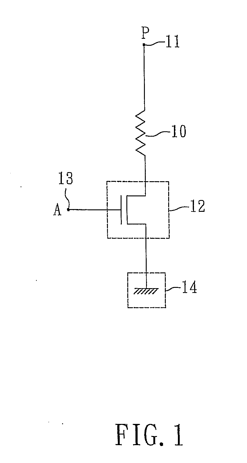
CROSS REFERENCE TO RELATED APPLICATION[0001]This application claims the benefits of the China Patent Application Serial Number 201110080632.X, filed on Mar. 23, 2011, the subject matter of which is incorporated herein by reference.BACKGROUND OF THE INVENTION[0002]1. Field of the Invention[0003]The present invention relates to an ink-jet head and, more particularly, to an ink-jet head adaptive for the single-color ink-jet printing or the multi-colors ink-jet printing.[0004]2. Description of Related Art[0005]In the present ink-jet printing field, the best and most effective way for improving the printing resolution and increasing the printing speed is to increase the number of the heating elements on the ink-jet chip directly, i.e. increasing the number of nozzles. In addition, the conventional method for controlling the operation of the heating element, the heating elements are controlled by the control contacts in the one-on-one manner.[0006]Please refer to FIG. 1, wherein FIG. 1 is...

Claims


Application Information

Patent Timeline
Patent Type & Authority Applications(United States)
IPC IPC(8): B41J2/175
CPCB41J2/04541B41J2/14072B41J2/0458B41J2/04543
Inventor MOU, HAO JANHSUEH, TA WEICHANG, YING LUNYU, RONG HOTAI, HSIEN CHUNGCHANG, CHENG MINGLIAO, WEN HSIUNGHAN, YUNG LUNG
Owner MICROJET TECH
Learn More