Heart pump controller

a heart pump and controller technology, applied in the field of controllers for heart pumps, can solve the problems of increasing the use of mechanical device therapy for treating heart failure, unsuitable for implantation in a subject, and limited number of donor organs for heart transplantation, and achieve the effect of reducing the outlet flow pressur

Active Publication Date: 2012-09-27
BIVACOR
View PDF2 Cites 79 Cited by
  • Summary
  • Abstract
  • Description
  • Claims
  • Application Information

AI Technical Summary

Benefits of technology

[0057]d) causing the magnetic bearing to control the axial position of the impeller in accordance with the indicator to thereby control a fluid flow between the inlets and the outlets.
[0118]iv) causing the magnetic bearing to control the axial position of the impeller in accordance with the indicator to thereby control a fluid flow between the inlets and the outlets.

Problems solved by technology

The use of mechanical device therapy to treat heart failure is increasing as the general population ages and the number of donor organs for heart transplantation remains limited.
In addition, it is necessary to control the blood pumps so that a discharge amount from the left ventricle blood pump becomes different than that from the right ventricle blood pump, but since only one pump chamber is provided in the pump using the rotating device disclosed in Japanese Patent Publication No. 3930834, two separate pumps, one pump for pumping blood through the body and the other pump for pumping blood to the lungs, are required when applying to the above-described blood pump, and thus there are problems that a pump apparatus becomes large and complicated, making it unsuitable for implantation in a subject.
First generation pulsatile devices necessitate contacting components, which limits their predicted mechanical lifetime below three years.
However, initial techniques for impeller support also imposed significant limitations on device lifetime, as they required a shaft, seals and bearings U.S. Pat. No. 4,589,822.
However, all currently available bi-ventricular assist systems require the use of two devices, with separate controllers, which can introduce left and right outflow control issues, particularly with the second and third generation devices.
The dual device approach also increases implantation size as well as the cost of the therapy.
This effectively introduces an inherent problem regarding the ability to independently control and thus balance the outflow from the left and right sides of the device, i.e. an increase in impeller rotational speed with produce a corresponding increase in outflow from both cavities.
This method of control would inherently consume excessive amounts of electrical power.
These components increase the possibility of device failure; as such components have limited long term reliability.
Furthermore, their addition to the device can induce extra blood contact with other foreign material, exacerbating the potential for blood damage.
However, this technique introduces an additional blood contacting conduit, as well as complexities involved with active feedback control, such as the need for sensors.
Furthermore, this solution can help to balance the fluid distribution but does not provide a method for controlling the alteration of device outflow.
However, no significant effect on pump outflow can be observed with this motion, as altering radial clearance gaps has minimal effect on hydraulic efficiency.
Whilst this motion can be adapted to alter the outflow of the device, motion in the same direction as the applied force is undesirable, and will, for example, increase outflow when a decrease is warranted.
Since this configuration uses repelling magnets to achieve this, their low stiffness may not provide sufficient counteraction of force for a given displacement.
Although axial relocation is opposite to the direction of the applied force, the shrouded configuration as well as the location of the impeller vanes beneath the impeller does not provide for a reduction in pump outflow in response to the forces generated during instances of ventricular collapse.
Therefore, the zero power controller can minimise bearing bower, but not provide flow control based on changing preload conditions.
Furthermore, the mentioned axial gap between the bottom impeller shroud and casing (0.005 inch) is too small, and impeller blade height too large, to produce an appreciable change in hydraulic performance with the maximum axial translation possible, even if the shroud was semi-open.

Method used


Image

  • Heart pump controller
  • Heart pump controller
  • Heart pump controller

Examples


Embodiment Construction

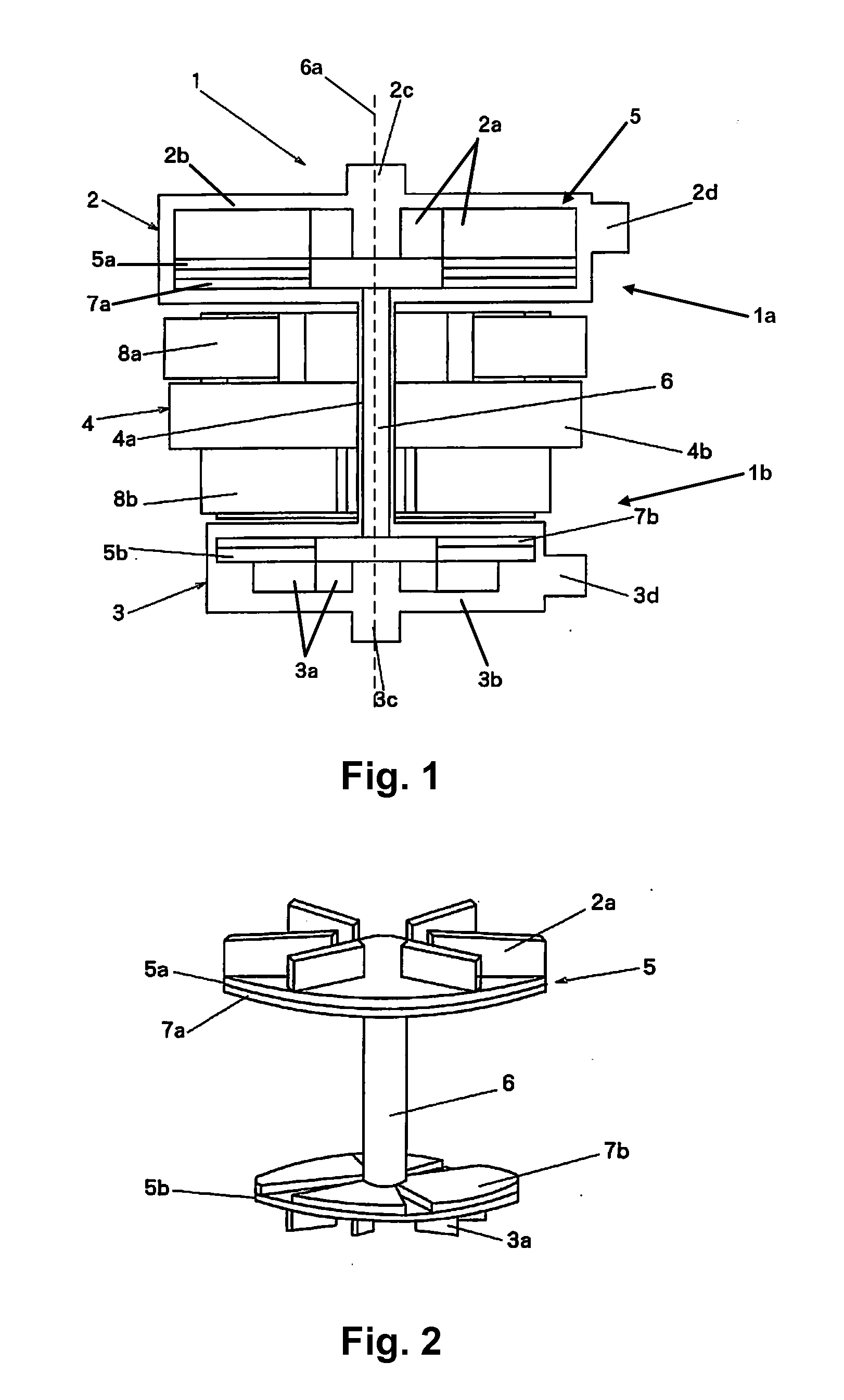
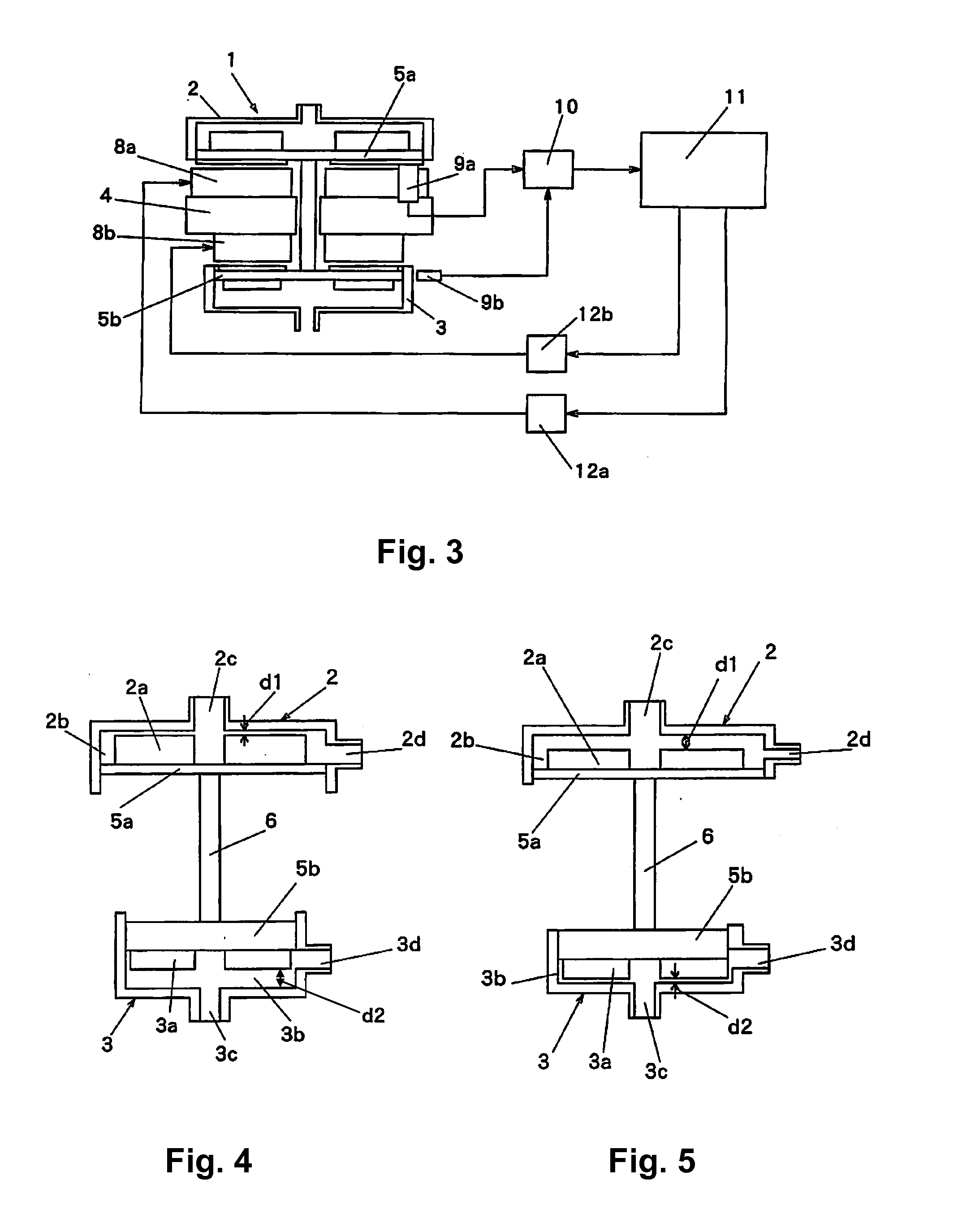
[0166]A first example of a pump apparatus will now be described with reference to FIGS. 1 to 5. In particular, FIG. 1 is a sectional view of a pump apparatus 1, and FIG. 2 is a perspective view of first and second rotors of the pump apparatus 1.

[0167]In this example, a first pump 2 is arranged in a first part 1a of the pump apparatus 1, and a second pump 3 is arranged in a second part 1b of the pump apparatus 1. In this example, at least part of a magnetic bearing and / or a drive, in this example a stator 4, is provided between the first and the second pumps 2, 3.

[0168]The pump apparatus includes an impeller 5, having a first rotor 5a and a second rotor 5b arranged in the first and second parts 1a, 1b, with the stator 4 being provided therebetween. The first and second rotors 5a, 5b are connected via a shaft 6 rotatably mounted within the pump apparatus to allow rotation about, and axial movement along an axis 6a in the connecting tube 4a, which in this example extends through the st...


PUM


Abstract

A heart pump including first and second cavities, each cavity including a respective inlet and outlet, a connecting tube extending between the first and second cavities, an impeller including: a first set of vanes mounted on a first rotor in the first cavity portion; a second set of vanes mounted on a second rotor in the second cavity portion; and, a shaft connecting the first and second rotors, the shaft extending through the connecting tube, a drive for rotating the impeller and a magnetic bearing including at least one bearing coil for controlling an axial position of the impeller, at least one of the drive and magnetic bearing being mounted outwardly of the connecting tube, at least partially between the first and second cavity portions.

Description

BACKGROUND OF THE INVENTION[0001]The present invention relates to a controller for a heart pump and method of controlling a heart pump.DESCRIPTION OF THE PRIOR ART[0002]The reference in this specification to any prior publication (or information derived from it), or to any matter which is known, is not, and should not be taken as an acknowledgment or admission or any form of suggestion that the prior publication (or information derived from it) or known matter forms part of the common general knowledge in the field of endeavour to which this specification relates.[0003]The use of mechanical device therapy to treat heart failure is increasing as the general population ages and the number of donor organs for heart transplantation remains limited. Devices can be used to bridge a patient to heart trans-plant, to recovery, or indeed as a destination alternative. The latter support strategy requires a device with increased mechanical durability / lifetime.[0004]A blood pump used for an arti...

Claims


Application Information

Patent Timeline
Patent Type & Authority Applications(United States)
IPC IPC(8): A61M1/10
CPCA61M1/101A61M1/1086F04D13/0666A61M1/1015F04D29/048F04D13/0633F04D13/064F04D29/042A61M1/122A61M2205/3334A61M60/422A61M60/232A61M60/585A61M60/824A61M60/554A61M60/237A61M60/178A61M60/196A61M60/538A61M60/822A61M60/148
Inventor MASUZAWA, TORUSASAKI, EISUKETIMMS, DANIEL
Owner BIVACOR
Why Eureka
Try Eureka