Flow estimation in a blood pump

a technology of flow estimation and blood pump, which is applied in the field of blood pump, can solve the problems of undesirable conditions, device not providing sufficient circulatory assistance to the patient, and device failure to provide sufficient patient circulatory assistan

Active Publication Date: 2012-09-27
HEARTWARE INC
View PDF4 Cites 156 Cited by
  • Summary
  • Abstract
  • Description
  • Claims
  • Application Information

AI Technical Summary

Benefits of technology

[0006]One aspect of the invention provides an implantable blood pump system. The system according to this aspect of the invention desirably comprises a pump and a control circuit. The pump includes a housing having an axis, and a rotor disposed within the housing, the rotor being rotatable around the axis. The control circuit is operatively coupled to the pump and configured to...

Problems solved by technology

This condition is undesirable.
If the flow rate through the pump is insufficient, the device will not pr...

Method used


Image

  • Flow estimation in a blood pump
  • Flow estimation in a blood pump
  • Flow estimation in a blood pump

Examples


Embodiment Construction

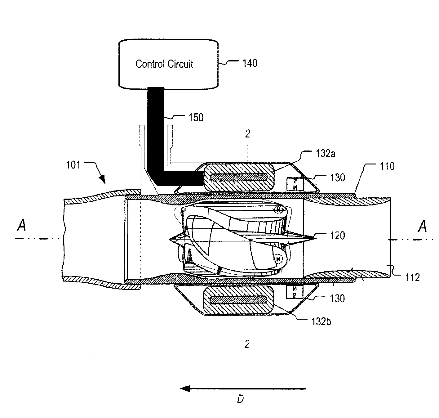
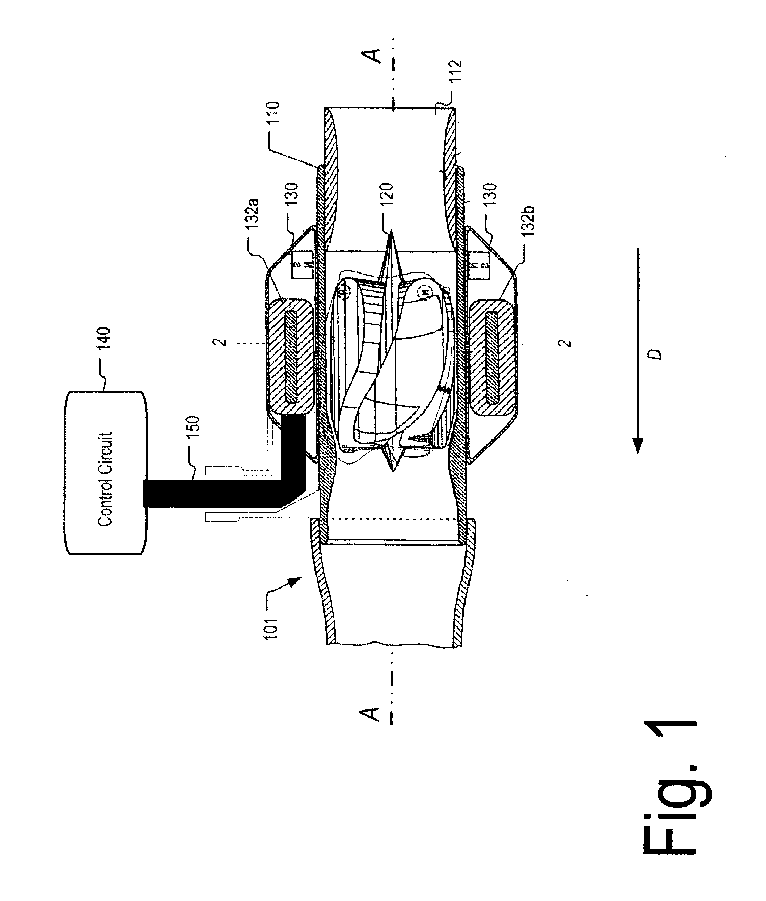
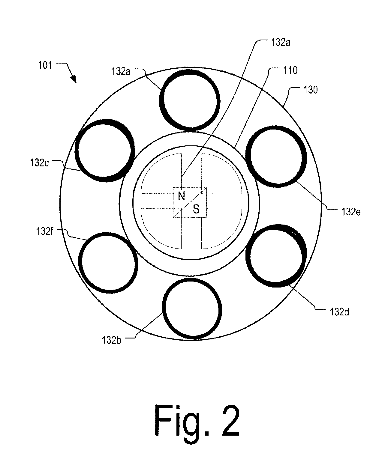
[0018]FIGS. 1-3 depict a blood pump system 100 in accordance with one embodiment of the invention. The blood pump system 100 according to this embodiment includes a control circuit 140 connected via a cable feed 150 to a blood pump 101. The blood pump 101 includes a housing 110 defining a bore 112 having an axis A. A rotor 120 is disposed within the bore. The rotor 120 has a permanent magnetization with flux direction perpendicular to the axis of the bore. The rotor constitutes an impeller configured to push blood in a downstream direction D parallel to the bore 112 when the rotor is turning.

[0019]The pump also includes a stator 130. The stator includes coils 132a-e (FIG. 2) connected in a WYE or delta configuration and placed around the circumference of the housing 110. The coils are arranged in pairs diametrically opposed to one another. Thus, coils 132a and 132b form one pair, coils 132c and 132d form another pair, and coils 132e and 132f form another pair. When the coils are dri...


PUM


Abstract

The flow rate of blood in an implantable blood pump is determined at least in part based on a parameter related to thrust on the rotor of the pump. The parameter may be a parameter related to displacement of the rotor along its axis, such as a function of the back electromotive force generated in one or more coils of the stator. The back electromotive force may be measured during open-phase periods of a particular coil or set of coils, during which no power is applied to the coil or set of coils by the motor drive circuit. The parameter related to thrust may be used in conjunction with the speed of rotation of the rotor, the magnitude of current supplied to the rotor, or both to determine the flow rate. The pump may be controlled responsive to the determined flow rate.

Description

CROSS-REFERENCE TO RELATED APPLICATIONS[0001]The present application claims the benefit of the filing date of U.S. Provisional Patent Application No. 61 / 434,894, filed Jan. 21, 2011, the disclosure of which is hereby incorporated herein by reference.FIELD OF THE INVENTION[0002]The present invention relates to blood pumps, to methods of using blood pumps, and to control circuits adapted for use with blood pumps.BACKGROUND OF THE INVENTION[0003]Implantable blood pumps may be used to provide assistance to patients with late stage heart disease. Blood pumps operate by receiving blood from a patient's vascular system and impelling the blood back into the patient's vascular system. By adding momentum and pressure to the patient's blood flow, blood pumps may augment or replace the pumping action of the heart. For example, a blood pump may be configured as ventricular assist device or “VAD.” Where a VAD is used to assist the pumping action of the left ventricle, the device draws blood from ...

Claims


Application Information

Patent Timeline
IPC IPC(8): A61M1/10
CPCA61M1/101A61M1/122A61M1/1086A61M2205/3334A61M60/148A61M60/585A61M60/242A61M60/546A61M60/824A61M60/422A61M60/237A61M60/538A61M60/178A61M60/825A61M60/822
Inventor CASAS, FERNANDOREYES, CARLOS
Owner HEARTWARE INC
Why Eureka
Try Eureka