Steering device

a steering device and steering technology, applied in the direction of steering parts, vehicle components, transportation and packaging, etc., can solve the problems of deterioration of telescopic operation, further cost increase, etc., to prevent twisting, improve clamping rigidity, and improve clamping rigidity

Active Publication Date: 2012-10-04
YAMADA SEISAKUSHO KK
View PDF3 Cites 15 Cited by
  • Summary
  • Abstract
  • Description
  • Claims
  • Application Information

AI Technical Summary

Benefits of technology

[0026]In the second invention, the rear extension side portion of the pivot bracket fixedly contacts the upper portion contact surface formed on the outer surface on either width direction side of the outer column, while the fixing bracket sandwiches the two rear extension side portions and the two lower portion contact surfaces of the outer column using the two fixing side portions and connects these components so that the components can be clamped and released via the clamping tool. In other words, the outer column and the pivot bracket are clamped integrally, and therefore the inner column can be clamped fixedly by the upper portion contact surfaces and lower portion contact surfaces of the outer column, leading to an improvement in clamping rigidity.
[0027]In the third invention, the width direction dimension of the step portion formed between the upper portion contact surface and the lower portion contact surface is set to be equal to or smaller than the thickness dimension of the rear extension side portion, and therefore, during clamping, the two fixing side portions of the fixing bracket come into contact with the two rear extension side portions of the pivot bracket first such that the upper portion contact surfaces are pressed thereby. Thus, the outer column can be prevented from twisting. Further, the inner column is pressed from the upper portion contact surface of the outer column, which is provided in a position corresponding to a horizontal diameter line passing through the diametrical center, and therefore the inner column receives an even pressing force from the holding inner peripheral surface of the outer column. As a result, the clamping rigidity can be improved and rattling can be prevented.
[0028]In the fourth invention, the groove-shaped recessed portion is formed in an up-down direction intermediate location in the holding inner peripheral surface of the outer column so as to extend in an axial direction, and therefore the clamping force from the upper portion contact surface is dispersed evenly between the holding inner peripheral surface in a region above the recessed portion and the holding inner perip

Problems solved by technology

Furthermore, dimension management of the engagement projections 83A, 83B, the engagement recesses 12A, 12B in the outer column 1, and the engagement recesses 27A, 27B in the inner column 2 is di

Method used


Image

  • Steering device
  • Steering device
  • Steering device

Examples


Embodiment Construction

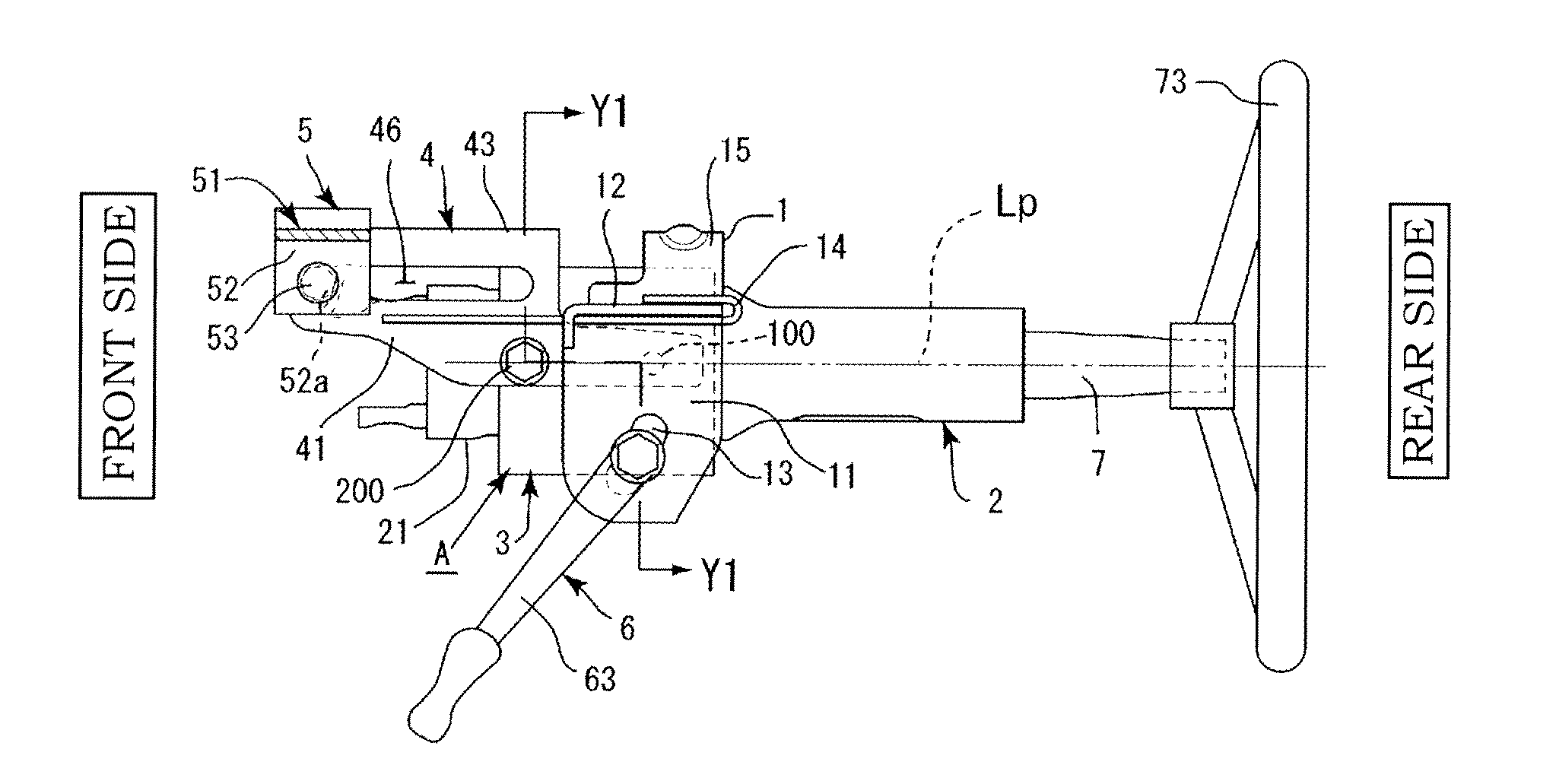
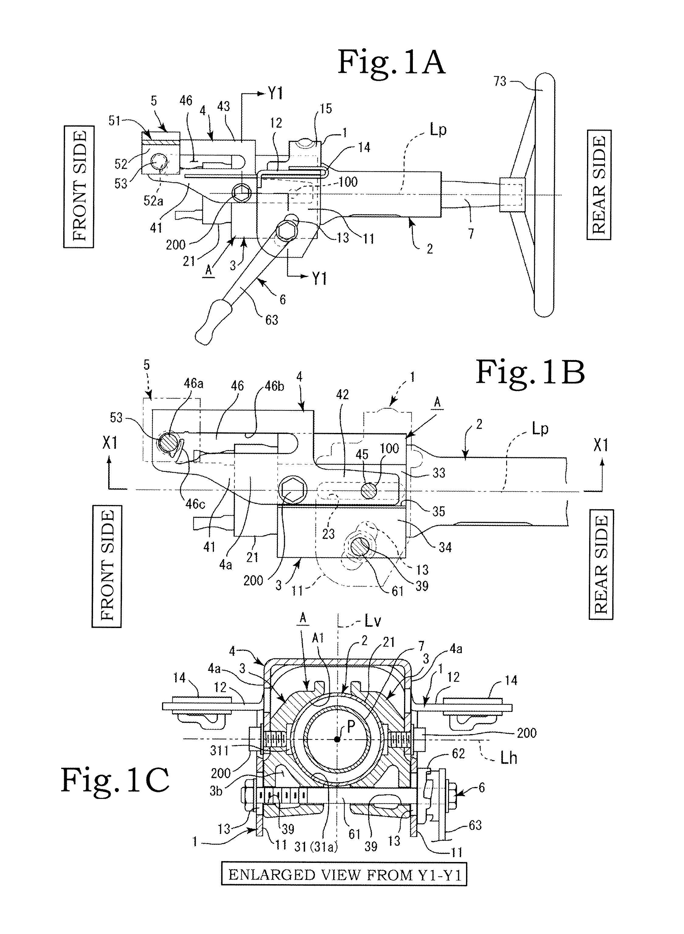
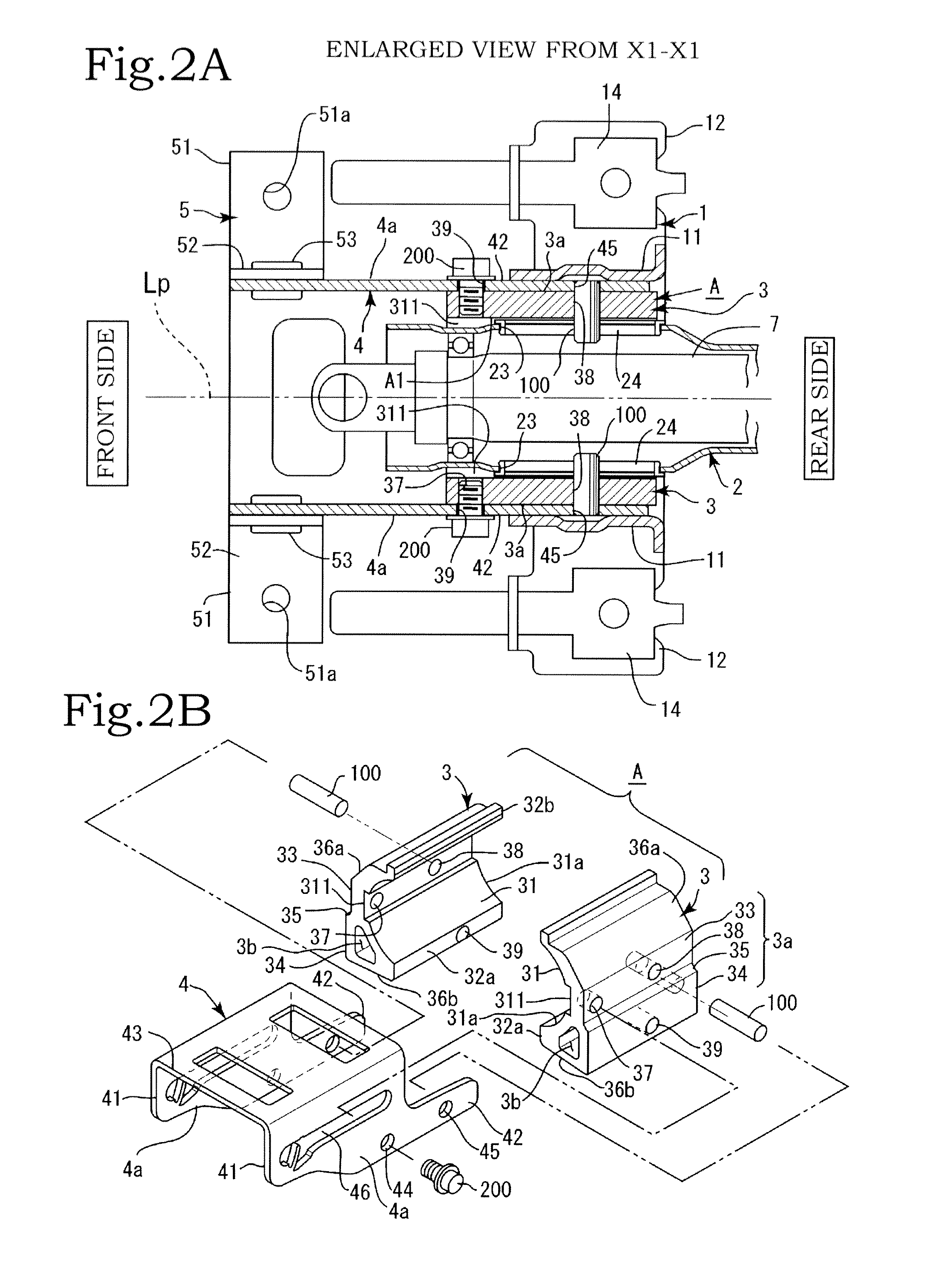
[0042]Embodiments of the present invention will be described below on the basis of the drawings. Note that in the following description of the present invention, a front-rear direction is set such that when the steering device according to the present invention is mounted in an automobile, a side corresponding to a front of the automobile is assumed to be a “front side” and a side corresponding to a rear of the automobile is assumed to be a “rear side”, using a front-rear direction of the automobile as a reference. Further, a direction linking the front side to the rear side will be referred to as an “axial direction”. Furthermore, a “width direction” indicates a left-right direction of the automobile.

[0043]As shown in FIGS. 1 to 3, the present invention is principally constituted by a fixing bracket 1, an inner column 2, an outer column A, a pivot bracket 4, a clamping tool 6, and so on. The fixing bracket 1 is constituted by fixing side portions 11 and attachment portions 12 forme...


PUM


Abstract

A steering device includes: an inner column; an outer column that includes a left-right pair of outer column half bodies having holding surface portions formed on respective inner surface sides thereof, the two holding surface portions together constituting a holding inner peripheral surface for holding an outer peripheral surface of the inner column; a pivot bracket in which hanging side portions are formed on either width direction side of a pivot upper portion; a fixing bracket provided with fixing side portions on either width direction side; and a clamping tool. Respective width direction outside surfaces of the two outer column half bodies are sandwiched between the two hanging side portions of the pivot bracket, and the two fixing side portions of the fixing bracket are connected such that the two width direction outside surfaces of the two outer column half bodies can be clamped and released by the clamping tool.

Description

BACKGROUND OF THE INVENTION[0001]1. Field of the Invention[0002]The present invention relates to a steering device including a tilt / telescopic adjustment mechanism, with which a clamping condition during tilt / telescopic adjustment can be strengthened and rattling throughout the entire device can be prevented.[0003]2. Description of the Related Art[0004]In Japanese Patent Application Publication No. 2010-105662, a left / right pair of clamp members 8A, 8B molded from an aluminum alloy or a magnesium alloy using a die casting method are sandwiched to be capable of telescopic movement and tilting movement between inner peripheral surfaces 321A, 321B of left and right side plates 32A, 32B of an upper side vehicle body attachment bracket 3, and arc-shaped inner peripheral surfaces 82A, 82B formed on respective inner sides of the clamp members 8A, 8B surround and hold an outer periphery 11 of an outer column 1 (see (2) of FIG. 2 and FIG. 3 in Japanese Patent Application Publication No. 2010...

Claims


Application Information

Patent Timeline
IPC IPC(8): B62D1/187
CPCB62D1/184B62D1/187B62D1/185
Inventor MANIWA, TAKAHIROYOKOTA, NORIHIKO
Owner YAMADA SEISAKUSHO KK
Why Eureka
Try Eureka