A polygonal cutting insert and a cutting tool with a raised portion in the hole
A technology of cutting inserts and protrusions, applied in cutting inserts, tools for lathes, turning equipment, etc., can solve the problems of chipping cutting life, low cutting efficiency, deformation of fasteners, etc. of cutting inserts, so as to avoid cutting Vibration, improved cutting accuracy, and improved clamping rigidity
- Summary
- Abstract
- Description
- Claims
- Application Information
AI Technical Summary
Problems solved by technology
Method used
Image
Examples
Embodiment 1
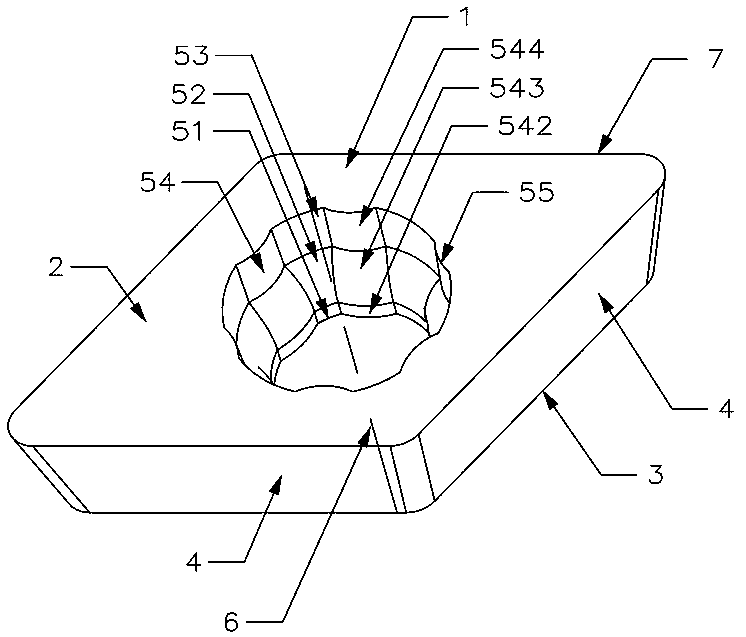
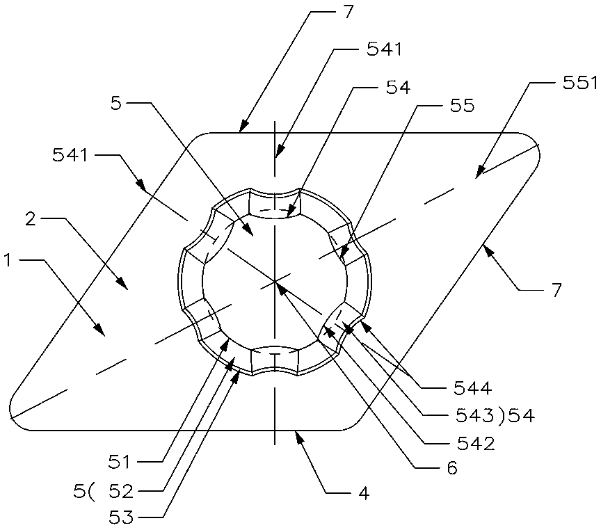
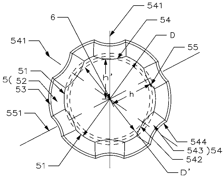
[0037] Such as Figure 1 to Figure 5 As shown, the polygonal cutting insert with protrusions in the hole of this embodiment includes a blade body 1 composed of an upper surface 2, a lower surface 3, and a plurality of side surfaces 4 connecting the upper surface 2 and the lower surface 3. The blade body 1 There is a central hole 5 that runs through the upper surface 2 and the lower surface 3. The blade body 1 is symmetrical about the central axis 6 of the central hole 5. Each side 4 intersects with the upper surface 2 to form a plurality of cutting edges 7. The inner surface of the central hole 5 corresponds to Each side 4 is provided with a raised portion 54 , and the raised portion 54 faces the corresponding side 4 .
[0038] In this embodiment, the blade body 1 is a parallelogram-shaped blade body as an example. The blade body 1 is provided with two sets of positioning sides, the positioning sides are composed of two adjacent sides 4, one set is the sides 4 on both sides o...
Embodiment 2
[0048] Such as Figure 6 As shown, the cutting tool of this embodiment includes a cutter body 10 and a fastening screw 11, and the cutter body 10 is provided with a sipe 101, including the cutting blade in Embodiment 1, and the cutting blade is installed in the sipe 101, tightly The set screw 11 is located in the central hole 5 and presses the cutting insert into the sipe 101. The cutter body 10 is a square cutter bar, only offers a knife groove 101 on the cutter body 10, and the cutting blade cooperates with the positioning surface of the knife groove 101 through a group of positioning sides. It is installed in the knife groove 101 through another set of positioning sides. The number of fastening screws 11 in contact with the protrusions 54 is three to six in the central hole 5 .
[0049] In this embodiment, the fastening screw 11 forms discontinuous contact with two adjacent protrusions 54 (the protrusions 54 on both sides of an acute angle) in the central hole 5, and the ...
Embodiment 3
[0053] Such as Figures 7 to 10 As shown, this embodiment is roughly the same as Embodiment 1, the only difference being:
[0054] In this embodiment, the blade body 1 is in the shape of a square plate, and four corner protrusions 55 are arranged to face the four right angles of the blade body 1 respectively. Group positioning sideways. With the change of the cutting force, an eight-fold constraint overclamping positioning can be formed in the center hole 5 of the insert body 1, and the principle is the same as that of the first embodiment.
[0055] In this embodiment, the blade body 1 has a horizontal middle section 9, the blade body 1 is symmetrical about the horizontal middle section 9, the inner surface of the center hole 5 above the horizontal middle section 9 and the inner surface of the center hole 5 below the horizontal middle section 9 are both A raised portion 54 is provided. Four cutting edges 7 are also formed between the lower surface 3 and the side surface 4, ...
PUM
 Abstract
Description
Claims
Application Information
 - R&D
- Intellectual Property
- Life Sciences
- Materials
- Tech Scout
- Unparalleled Data Quality
- Higher Quality Content
- 60% Fewer Hallucinations
Browse by: Latest US Patents, China's latest patents, Technical Efficacy Thesaurus, Application Domain, Technology Topic, Popular Technical Reports.
© 2025 PatSnap. All rights reserved.Legal|Privacy policy|Modern Slavery Act Transparency Statement|Sitemap|About US| Contact US: help@patsnap.com


