A tool box fixture for machining piston ring grooves

A technology of piston ring groove and ring groove cutter, which is applied in the direction of manufacturing tools, metal processing equipment, metal processing machinery parts, etc., can solve the problems of small handle size, influence of ring groove cutter rigidity, and inability to cool, so as to improve clamping Rigidity, strong clamping stability, firm and reliable clamping effect

A technology of piston ring groove and ring groove cutter, which is applied in the direction of manufacturing tools, metal processing equipment, metal processing machinery parts, etc., can solve the problems of small handle size, influence of ring groove cutter rigidity, and inability to cool, so as to improve clamping Rigidity, strong clamping stability, firm and reliable clamping effect

CN105033678BActive Publication Date: 2017-03-29成都银河动力有限公司

Image

  • A tool box fixture for machining piston ring grooves
  • A tool box fixture for machining piston ring grooves
  • A tool box fixture for machining piston ring grooves

Examples


Embodiment Construction

[0030] The present invention will be further described below in conjunction with accompanying drawing, protection scope of the present invention is not limited to the following:

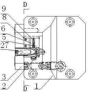
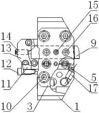
[0031] Such as figure 1 , figure 2 , image 3 As shown, a knife box fixture for processing piston ring grooves includes a knife box body 1, a side pressure knife plate 3, an annular groove knife 9 and an annular groove knife fixture. The knife box body 1 is provided with a mounting groove 25, and the annular groove The knife 9 and the ring groove knife fixture are installed in the installation groove 25, and the side pressure knife plate 3 is installed on the side where the knife box body 1 is provided with the installation groove 25 through the side pressure knife plate mounting screw 10;

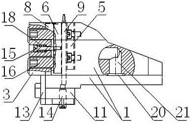
[0032] Such as Image 6 As shown, the ring groove knife holder includes a backing block A5, a backing block B6, a side compression screw 16, an elastic tensioning block 31 and an elastic tensioning screw 27, ...


PUM


Abstract

The invention discloses a knife box clamp for machining piston ring grooves. The knife box clamp for machining piston ring grooves comprises a knife box body (1), a side face knife clip (3), a ring groove knife (9) and a ring groove knife clamp. The knife box body (1) is provided with an installing groove (25). The ring groove knife (9) and the ring groove knife clamp are installed in the installing groove (25). The side face knife clip (3) is installed on the side, with the installing groove (25), of the knife box body (1) through side face knife clip installing screws (10). The ring groove knife clamp comprises a knife cushion block A (5), a knife cushion block B (6), side face pressing screws (16), an elastic expanding block (31) and elastic expanding screws (27). The bottom of the installing groove (25) is further provided with an elastic expanding screw installing block (2) through threads. The elastic expanding block (31) is arranged outside the elastic expanding screw installing block (2). The knife box clamp for machining piston ring grooves has the advantages that the knife box clamp can be used for clamping the ring groove knife for machining, and is high in rigidity, convenient to use, good in cooling and the like.

Description

technical field [0001] The invention relates to a machining fixture, in particular to a tool box fixture for machining piston ring grooves. Background technique [0002] The structure of the fine ring groove cutter box under the existing technical conditions is relatively simple, the size of the handle is small, and the overall rigidity is not ideal; there is no axial positioning device for the ring groove cutter during installation, so the installation position cannot be fixed when the ring groove cutter is replaced, and the In the process, the size of the piston ring groove changes greatly after the tool is changed, which is easy to cause process waste. Moreover, the knife box uses screws to press the ring groove knife from the side of the ring groove knife. Since the screw cannot be directly pressed on the ring groove knife, it is necessary to add side pads of different thicknesses on both sides of the ring groove knife. The side pads are usually made of some waste The r...

Claims


Application Information

Patent Timeline
29 Mar 2017
Publication
CN105033678B
IPC
B23Q3/00; B23Q11/00; B23Q11/10
CPC
B23Q3/00; B23Q11/0042; B23Q11/10
Inventors
温志高; 郭燕清