Machine tool and method for processing slender shaft parts

A technology of parts processing and processing methods, which is applied in the fields of CNC combined machine tools, machining manufacturing and automation, can solve the problems of low processing accuracy, difficult to guarantee processing accuracy, and poor product processing consistency, so as to improve production efficiency and production capacity, processing Good consistency and guaranteed machining accuracy

Active Publication Date: 2017-03-08
上海奇灏特自动化工程有限公司
View PDF7 Cites 0 Cited by
  • Summary
  • Abstract
  • Description
  • Claims
  • Application Information

AI Technical Summary

Problems solved by technology

[0002] In the current domestic and foreign automobile industry, before the forming and processing of a certain part involving a large number of applications, the raw material is a typical ultra-slender part. This part has an insurmountable processing technology, low processing accuracy, and poor product processing consistency. Bottleneck of inefficient production
At present, in China, the processing of the above-mentioned parts is usually completed by CNC transformation of ordinary lathe equipment. The processing method is to turn one end of the workpiece; disassemble the workpiece, turn around and clamp again, and turn the other end. low efficiency
The traditional clamping method is in the form of one clamp, one top and a heel tool rest (or center frame). The top holding effect of the tailstock will increase the instability and bending deformation in the processing of the slender shaft, and it is difficult to enhance the rigidity. role, making it difficult to guarantee machining accuracy
In foreign countries, special equipment is usually developed according to the parts process, but the price is very expensive
[0003] In view of the above problems, a machine tool and method for processing slender shaft parts are proposed, which effectively solve the problems of insufficient clamping rigidity, low machining accuracy, poor product processing consistency, and low production efficiency of slender parts. The field of manufacturing and automation has broad prospects

Method used


Image

  • Machine tool and method for processing slender shaft parts
  • Machine tool and method for processing slender shaft parts
  • Machine tool and method for processing slender shaft parts

Examples


Embodiment Construction

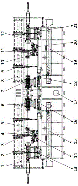
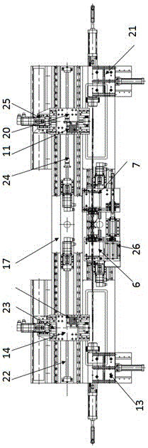
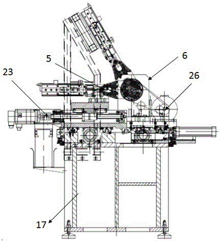
[0037] Such as figure 1 , 2 , 3, used for processing slender shaft parts, including the left clamping manipulator mounting seat 1, the left tail clamping mechanism 2, the left clamping manipulator 3, the left tool rest 4, and the left heel tool Manipulator unit 5, left headstock 6, right headstock 7, right clamping manipulator mount 8, right clamping manipulator 9, right follower manipulator unit 10, right tool rest 11, right tail clamp Pulling mechanism 12, slide table 13 of left tail clamping mechanism, left X-axis slide table 14, left chip conveyor 15, left Z2-axis transmission unit 16, frame 17, right Z2-axis transmission unit 18, left Side chip conveyor 19, right X-axis slide table 20, right tail clamping mechanism slide table 21, left Z1-axis transmission unit 22, left X-axis transmission unit 23, right Z1-axis transmission unit 24, right side X-axis transmission unit 25, main motor 26;

[0038]On the middle position of frame 17, left headstock 6 and right headstock 7...


PUM


Abstract

The invention discloses a machining tool and method for slender shaft type parts. The machining tool comprises a machine frame, a left spindle box, a left tail clamping and pulling mechanism, a left tool rest, a left tool following mechanical hand unit, a left X axis transmission unit, a left Z1 axis transmission unit, a left Z2 axis transmission unit, a left chip removal mechanism, a right spindle box, a right tail clamping and pulling mechanism, a right tool rest, a right tool following mechanical hand unit, a right X axis transmission unit, a right Z1 axis transmission unit, a right Z2 axis transmission unit and a right chip removal mechanism. The two ends of a workpiece are clamped at the same time through two sets of tailstock clamping mechanisms and a main transmission mechanism, and the tail throwing phenomenon of clamped slender parts is avoided; through the tail clamping and pulling mechanisms, tool following mechanical hands solve the problem that clamping rigidity of slender parts is not enough, and part machining precision is guaranteed; machining is carried out at the same time through two sets of executing devices, and the requirement for clamping force is lowered through the main cutting force equivalent counteraction principle; the purpose of obviously improving productivity is achieved.

Description

technical field [0001] The invention relates to a machine tool for processing slender shaft parts and a method thereof, belonging to the field of mechanical processing and manufacturing, automation, and numerical control combined machine tools. Background technique [0002] In the current domestic and foreign automobile industry, before the forming and processing of a certain part involving a large number of applications, the raw material is a typical ultra-slender part. This part has an insurmountable processing technology, low processing accuracy, and poor product processing consistency. Bottleneck of inefficient production. At present, in China, the processing of the above-mentioned parts is usually completed by CNC transformation of ordinary lathe equipment. The processing method is to turn one end of the workpiece; disassemble the workpiece, turn around and clamp again, and turn the other end. low efficiency. The traditional clamping method is in the form of one clamp...

Claims


Application Information

Patent Timeline
Patent Type & Authority Patents(China)
IPC IPC(8): B23B5/08B23B23/00
CPCB23B5/08B23B23/00
Inventor 黄小东姜杰凤郑希明郑国明
Owner 上海奇灏特自动化工程有限公司
Why Eureka
Try Eureka