

Substrate treatment apparatus and substrate treatment method
- Summary
- Abstract
- Description
- Claims
- Application Information
AI Technical Summary
Benefits of technology
Problems solved by technology
Method used
Image

Examples
first embodiment
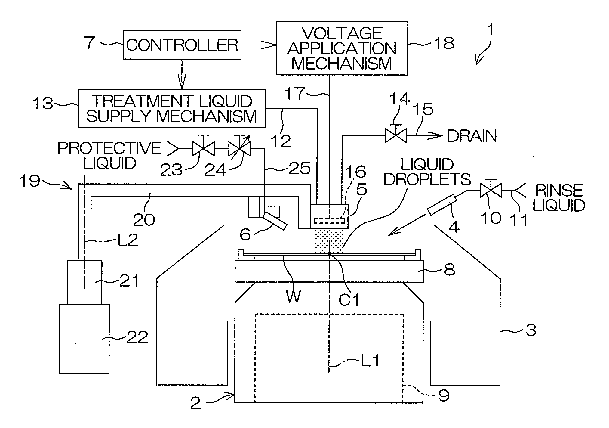
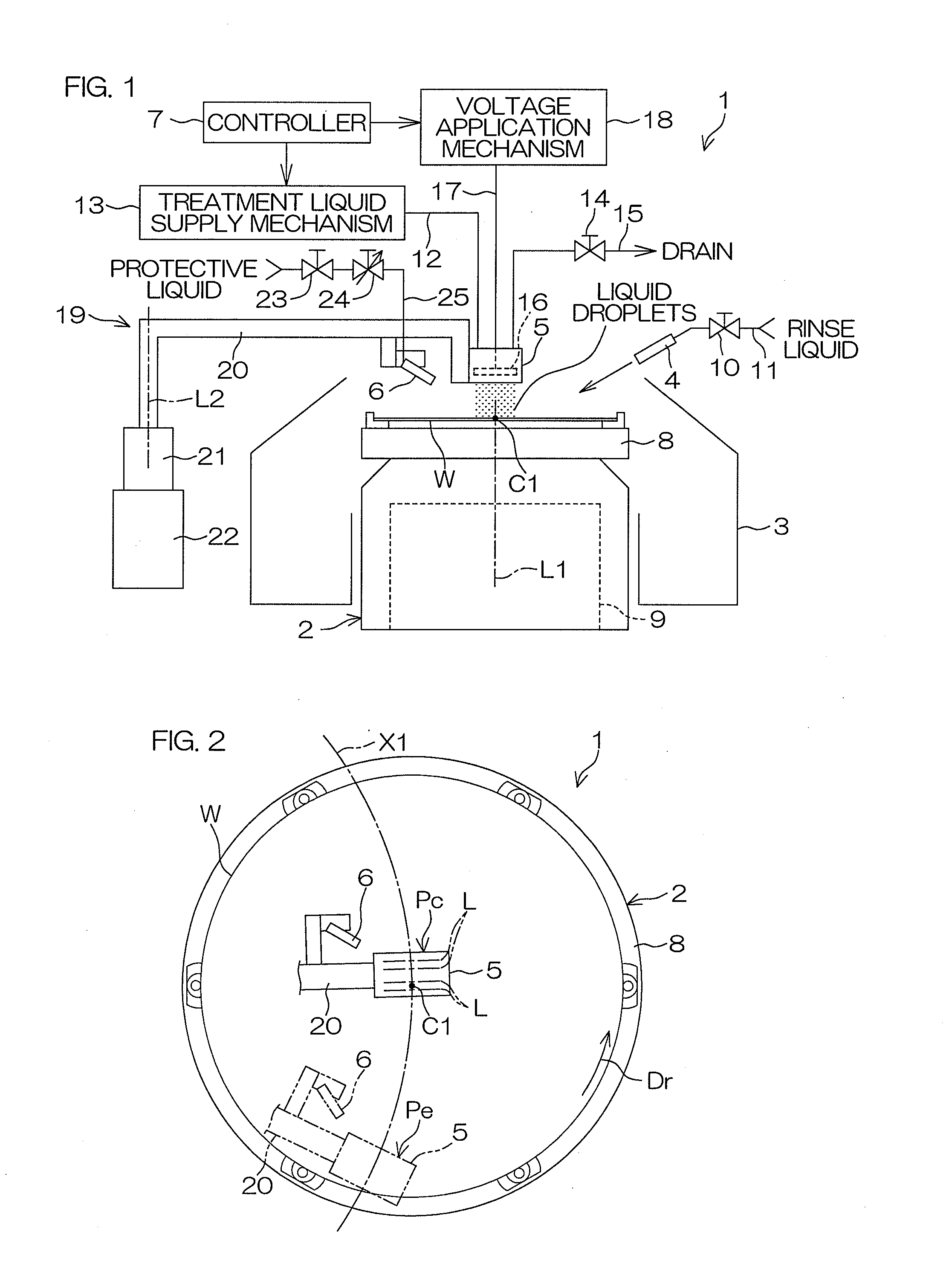
[0041]The spin chuck 2 includes a spin base 8 which horizontally holds the substrate W and is rotatable about a vertical rotation axis L1 extending through a center C1 of the substrate W, and a spin motor 9 which rotates the spin base 8 about the rotation axis L1. The spin chuck 2 may be a clamp chuck adapted to horizontally clamp the substrate W to horizontally hold the substrate W or a vacuum chuck adapted to suck a back surface (lower surface) of the substrate W serving as a non-device-formation surface to horizontally hold the substrate W. In the first embodiment, the spin chuck 2 is the clamp chuck.
[0042]The rinse liquid nozzle 4 is connected to a rinse liquid supply pipe 11 provided with a rinse liquid valve 10. With the rinse liquid valve 10 open, the rinse liquid is spouted from the rinse liquid nozzle 4 toward a center portion of the upper surface of the substrate W. With the rinse liquid valve 10 closed, on the other hand, the spouting of the rinse liquid from the rinse li...
second embodiment
[0091]Next, the present invention will be described. In FIG. 15, components corresponding to those shown in FIGS. 1 to 14 will be designated by the same reference characters as in FIGS. 1 to 14, and duplicate description will be omitted.
[0092]FIG. 15 is a schematic side view of a liquid droplet nozzle 205 and a protective liquid nozzle 6 according to the second embodiment of the present invention.
[0093]A substrate treatment apparatus 201 according to the second embodiment has substantially the same construction as the substrate treatment apparatus 1 according to the first embodiment, except for the liquid droplet nozzle. That is, the substrate treatment apparatus 201 includes liquid droplet nozzles 205, instead of the liquid droplet nozzle 5 according to the first embodiment, which generates treatment liquid droplets to be sprayed on spouting regions T201. In the second embodiment, the substrate treatment apparatus 201 includes two liquid droplet nozzles 205. The two liquid droplet ...
PUM
 Abstract
Description
Claims
Application Information