Fluid handling apparatus and fluid handling system

a technology of fluid handling and fluid handling, which is applied in the field of fluid handling apparatus and fluid handling system, can solve the problems of liquid leakage and contamination of the electrophoresis apparatus, and achieve the effect of preventing liquid leakage and preventing contamination of an external environmen

Inactive Publication Date: 2012-10-04
ENPLAS CORP
View PDF3 Cites 3 Cited by
  • Summary
  • Abstract
  • Description
  • Claims
  • Application Information

AI Technical Summary

Benefits of technology

[0011]The present invention forms a groove in a substrate member and can stop a liquid, leaked along a gap between the substrate member and the cover member produced by a thickness of a layered transfer function section, with the groove or can store the liquid in the groove, and can thereby prevent the liquid from leaking out and prevent contamination of an external environment.

Problems solved by technology

According to the above electrode forming method, the peripheral part of the carbon ink of the film or thin plate may remain unbonded (insufficiently laminated) to the chip body depending on the thickness of the carbon ink and the liquid may leak.
However, the background art adopts no measures for this liquid leakage, and the liquid leakage may cause contamination of the electrophoresis apparatus (electrode).

Method used


Image

  • Fluid handling apparatus and fluid handling system
  • Fluid handling apparatus and fluid handling system
  • Fluid handling apparatus and fluid handling system

Examples


Embodiment Construction

[0022]Hereinafter, an embodiment of the present invention will be described in detail with reference to the accompanying drawings. The following description is given using a micro-channel chip as a typical example of a fluid handling apparatus.

[0023][Configuration of Micro-Channel Chip]

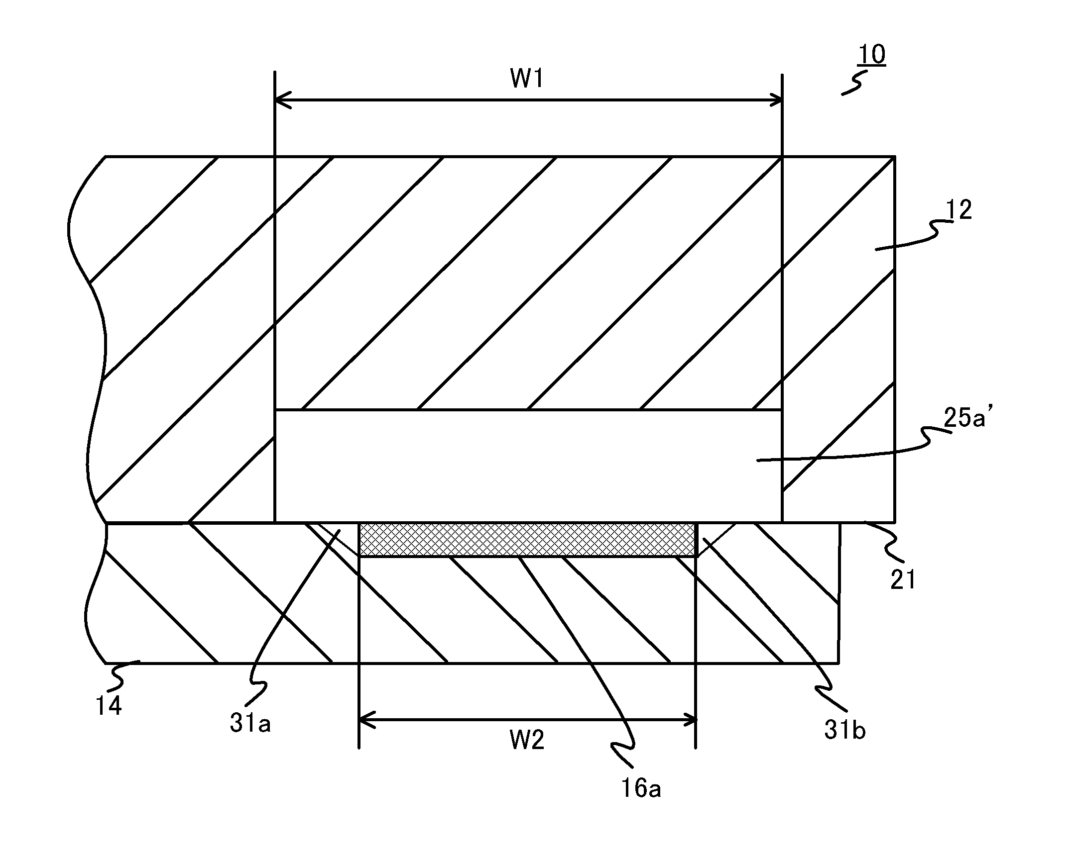
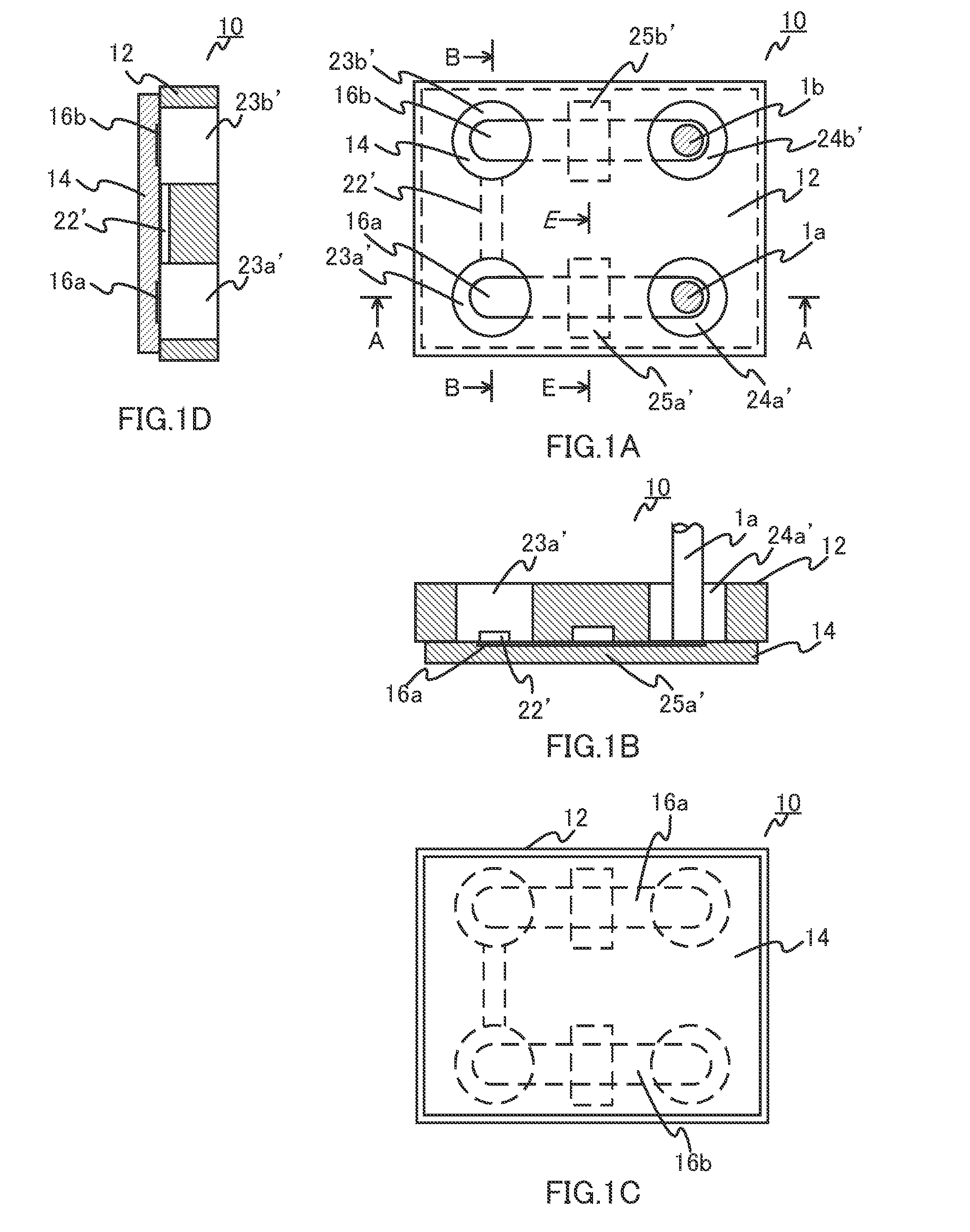
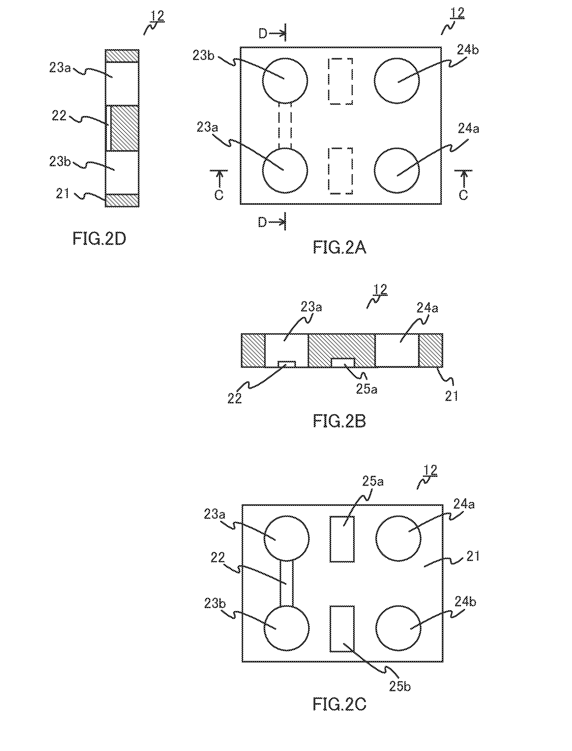
[0024]FIG. 1A to FIG. 1D are schematic views illustrating the shape of a micro-channel chip as a fluid handling apparatus according to the present embodiment. FIG. 1A is a plan view, FIG. 1B is a front cross-sectional view along line A-A, FIG. 1C is a bottom view and FIG. 1D is a left side cross-sectional view along line B-B. FIG. 1A and FIG. 1B also show electrode rods 1a and 1b together.

[0025]As shown in FIG. 1A to FIG. 1D, micro-channel chip 10 is constructed of a transparent substantially rectangular flat chip body (substrate member) 12, film (thin film which constitutes a cover member) 14 and carbon inks (electrodes as transfer function sections) 16a and 16b.

[0026]The thickness of chip body 12 i...


PUM


Abstract

Bottomed first regions 23a′ and 23b′, and second regions 24a′ and 24b′ are formed by joining film 14 to undersurface 21 of chip body 12 of a micro-channel chip. Third regions 25a′ and 25b′ are formed between first regions 23a′ and 23b′, and second regions 24a′ and 24b′ so as to be located on carbon inks 16a and 16b. The width of third regions 25a′ and 25b′ is formed so as to be greater than the width of carbon inks 16a and 16b.

Description

CROSS REFERENCE TO RELATED APPLICATIONS[0001]This application is entitled and claims the benefit of Japanese Patent Application No. 2011-082819, filed on Apr. 4, 2011, the disclosure of which including the specification, drawings and abstract is incorporated herein by reference in its entirety.TECHNICAL FIELD[0002]The present invention relates to a fluid handling apparatus and a fluid handling system provided therewith used for an analysis, processing or the like of a fluid sample.BACKGROUND ART[0003]In recent years, micro-analytical systems are used to carry out an inspection / analysis of trace substances such as proteins, nucleic acids (e.g., DNA) accurately and at high speed in the scientific field such as biochemistry and analytical chemistry or medical field.[0004]As an example of the micro-analytical system, there is a system which fills a channel formed on a micro-channel chip with a buffer solution, injects a sample from an injection port connected to the channel, applies a v...

Claims


Application Information

Patent Timeline
Patent Type & Authority Applications(United States)
IPC IPC(8): F16L53/00
CPCB01L3/502707G01N27/44791Y10T137/2224Y10T137/6606
Inventor NAKAO, TOMOKIONO, KOICHI
Owner ENPLAS CORP
Why Eureka
Try Eureka