Welding torch with wire feed speed control

a technology of speed control and welding torch, which is applied in the field of welding torch with wire feed speed control, can solve the problems of inadvertent adjustment, poor quality weld, and additional time and effort for the operator to monitor and readjust the weld parameters

Active Publication Date: 2012-10-04
ILLINOIS TOOL WORKS INC
View PDF2 Cites 73 Cited by
  • Summary
  • Abstract
  • Description
  • Claims
  • Application Information

AI Technical Summary

Benefits of technology

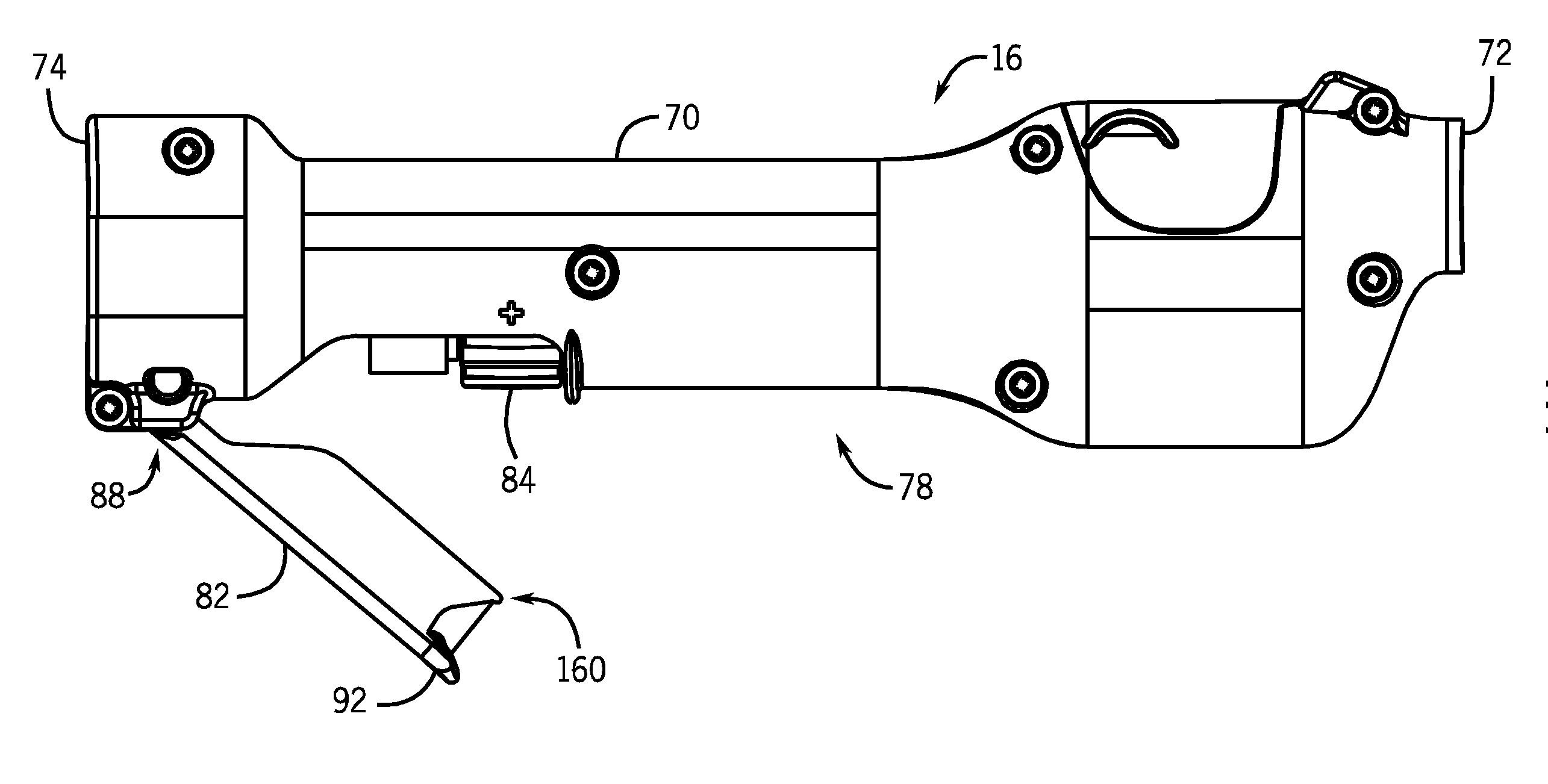
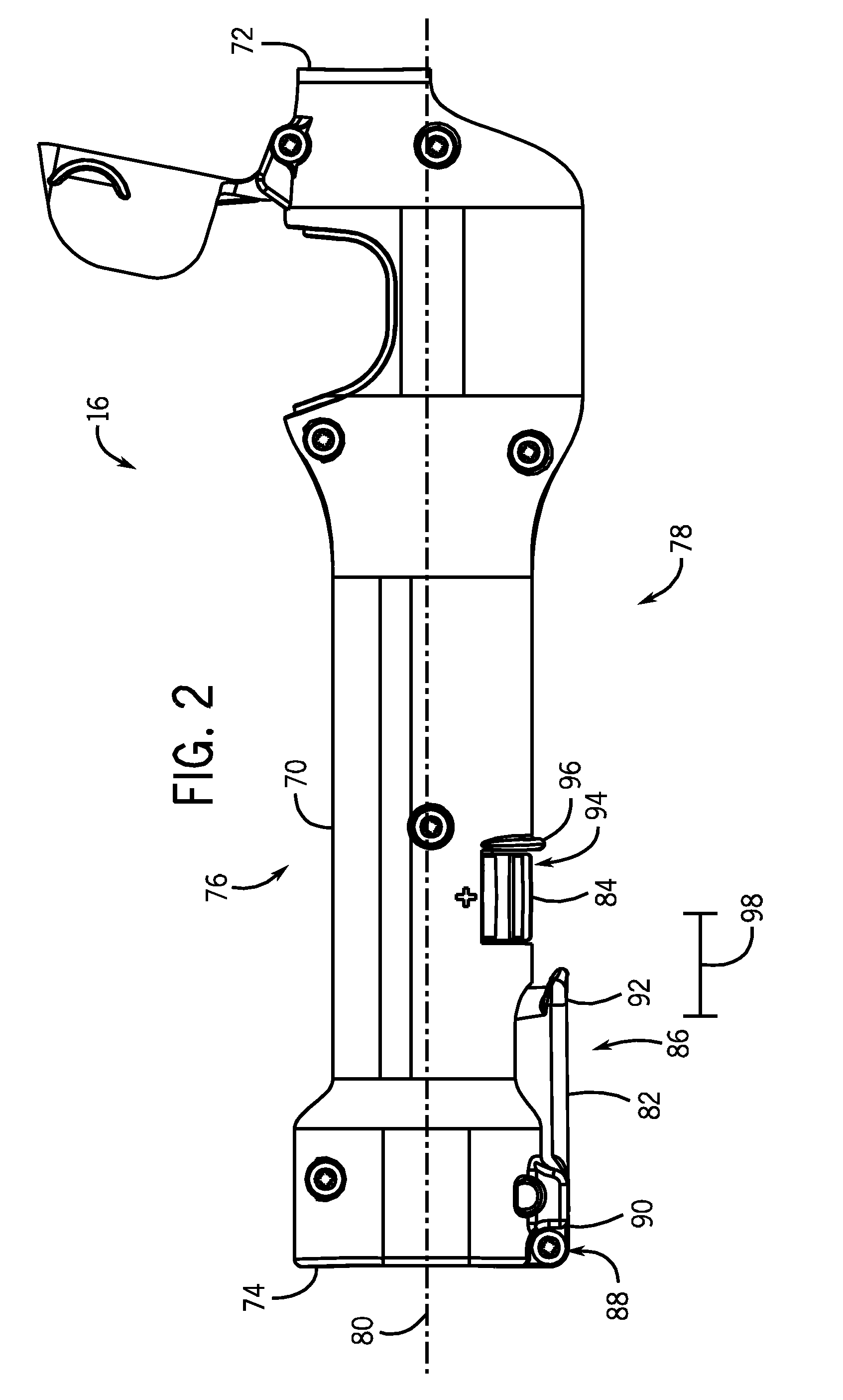
[0006]The present invention provides welding systems designed to permit adjustment of wire feed speed by an input device in a welding torch handle. A wire drive assembly is disposed in the torch handle and includes a drive motor and a drive roller. The wire drive assembly contacts a welding wire and is configured to drive the welding wire from a wire feeder to a welding operation. In addition, the welding torch handle has a trigger and a wire feed speed adjustment assembly. The trigger is disposed near a rear end of the torch handle and is configured to be depressed by an operator for initiating feed of the welding wire. The adjustment assembly is positioned near the rear end of the handle adjacent to the trigger and on the same side of the handle as the trigger. The adju

Problems solved by technology

In other cases, an adjustment is provided on the torch handle, but this may be subject to inadvertent adjustment due to its placement.
That is, the operator may mistakenly adjust the wire feed speed, or the welding torch may brush up against an obstacle, r

Method used


Image

  • Welding torch with wire feed speed control
  • Welding torch with wire feed speed control
  • Welding torch with wire feed speed control

Examples


Embodiment Construction

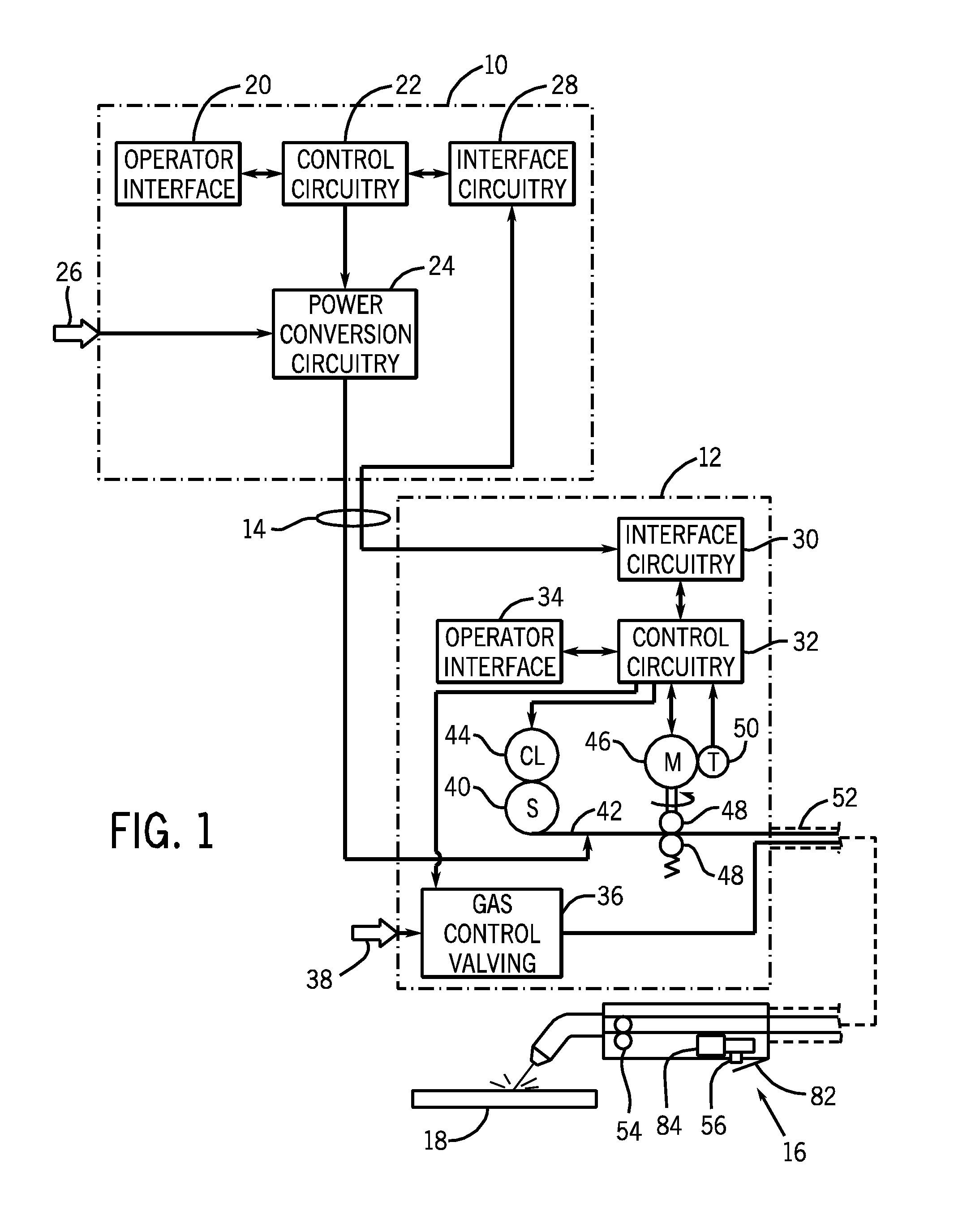
[0018]Turning now to the drawings, and referring first to FIG. 1, an exemplary welding system is illustrated as including a power supply 10 and a wire feeder 12 coupled to one another via conductors or conduits 14. In the illustrated embodiment the power supply 10 is separate from the wire feeder 12, such that the wire feeder may be positioned at some distance from the power supply near a welding location. However, it should be understood that the wire feeder 12, in some implementations, may be integral with the power supply. In such cases, the conduits 14 would be internal to the system. In embodiments in which the wire feeder is separate from the power supply, terminals are typically provided on the power supply and on the wire feeder to allow the conductors or conduits to be coupled to the systems so as to allow for power and gas to be provided to the wire feeder from the power supply, and to allow data to be exchanged between the two devices as described more fully below.

[0019]T...


PUM

PropertyMeasurementUnit
Speedaaaaaaaaaa

Abstract

A welding torch has a torch handle. A wire drive assembly is disposed in the torch handle and includes a drive motor and a drive roller. The wire drive assembly contacts the welding wire and is configured to drive the welding wire from a wire feeder to a welding operation. In addition, the welding torch has a trigger and a wire feed speed adjustment assembly. The trigger is disposed near a rear end of the torch handle and is configured to be depressed by an operator for initiating feed of the welding wire. The adjustment assembly is positioned near the rear end of the handle adjacent to the trigger and on the same side of the handle as the trigger. The adjustment assembly allows operator adjustment of a feed speed of the welding wire.

Description

CROSS REFERENCE TO RELATED APPLICATIONS[0001]This application is a Non-Provisional patent application of U.S. Patent Application No. 61 / 468,848, entitled “Novel Placement and Protection of Wire Feed Speed Control Knob on MIG Gun” and filed Mar. 29, 2011, which is herein incorporated by reference in its entirety.BACKGROUND[0002]The invention relates generally to welding torches, and more specifically, to systems that allow for operator adjustment of wire feed speeds in the torch handle.[0003]A wide range of welding systems and welding control regimes have been implemented for various purposes. For example, metal inert gas (MIG) techniques allow for formation of a continuing weld bead by feeding welding wire shielded by inert gas from a welding torch. Electrical power is applied to the welding wire and a circuit is completed through the workpiece to sustain an arc that melts the wire and the workpiece to form the desired weld.[0004]The welding torch may include features so that an ope...

Claims


Application Information

Patent Timeline
IPC IPC(8): B23K9/12
CPCB23K9/133B23K9/1336
Inventor GARVEY, PAUL WILLIAMROEHI, CHRIS J.
Owner ILLINOIS TOOL WORKS INC
Why Eureka
Try Eureka