Long endurance vertical takeoff and landing aircraft

a vertical takeoff and landing and long-range technology, applied in the field of aircraft designs, can solve the problems of large footprint of equipment, difficult urban basing, and difficulty in preparing launch and recovery sites

Active Publication Date: 2012-10-04
DZYNE TECH
View PDF7 Cites 142 Cited by
  • Summary
  • Abstract
  • Description
  • Claims
  • Application Information

AI Technical Summary

Benefits of technology

[0014]In some embodiments, an aircraft and, in particular, an aircraft capable of fixed wing and rotor flight modes is disclosed. A fixed wing flight mode is defined as flight in which a fuselage is substantially parallel to the ground and a rotor flight mode is defined as flight in which a fuselage is substantially perpendicular to the ground. The aircraft comprises a plurality of wings, each wing having a spar such that each wing is rotatable about the spar. The aircraft also comprises at least one actuator coupled to the spar of each of the plurality of wings. The aircraft further comprises a plurality of engines secured to said wings. The aircraft also comprises a fuselage further comprising a rotating support rotatable about a longitudinal axis of the fuselage wherein said plurality of wings are secured to the rotating support such that the wings rotate about a longitudinal axis of the fuselage.
[0015]In some embodiments, an aircraft and, in particular, an aircraft capable of fixed wing and rotor flight modes is disclosed. The aircraft comprise

Problems solved by technology

However, one major limitation of current UAVs is the need for prepared launch and recovery sites with large footprints or a traditional airport.
This equipment has many operational burdens.
This path must be obstacle-free over a mile or more beneath a 5 degree flight path, which makes urban basing very difficult.
These hybrid designs reduce the footprint necessary for launch and recovery but are more complex than either helicopters or conventional take off and landing aircraft as they generally incorporate multiple propulsion systems, each used for a different flight mode.

Method used


Image

  • Long endurance vertical takeoff and landing aircraft
  • Long endurance vertical takeoff and landing aircraft
  • Long endurance vertical takeoff and landing aircraft

Examples


Embodiment Construction

[0032]The following detailed description is directed to certain specific embodiments of the invention. However, the invention may be embodied in a multitude of different ways as defined and covered by the claims.

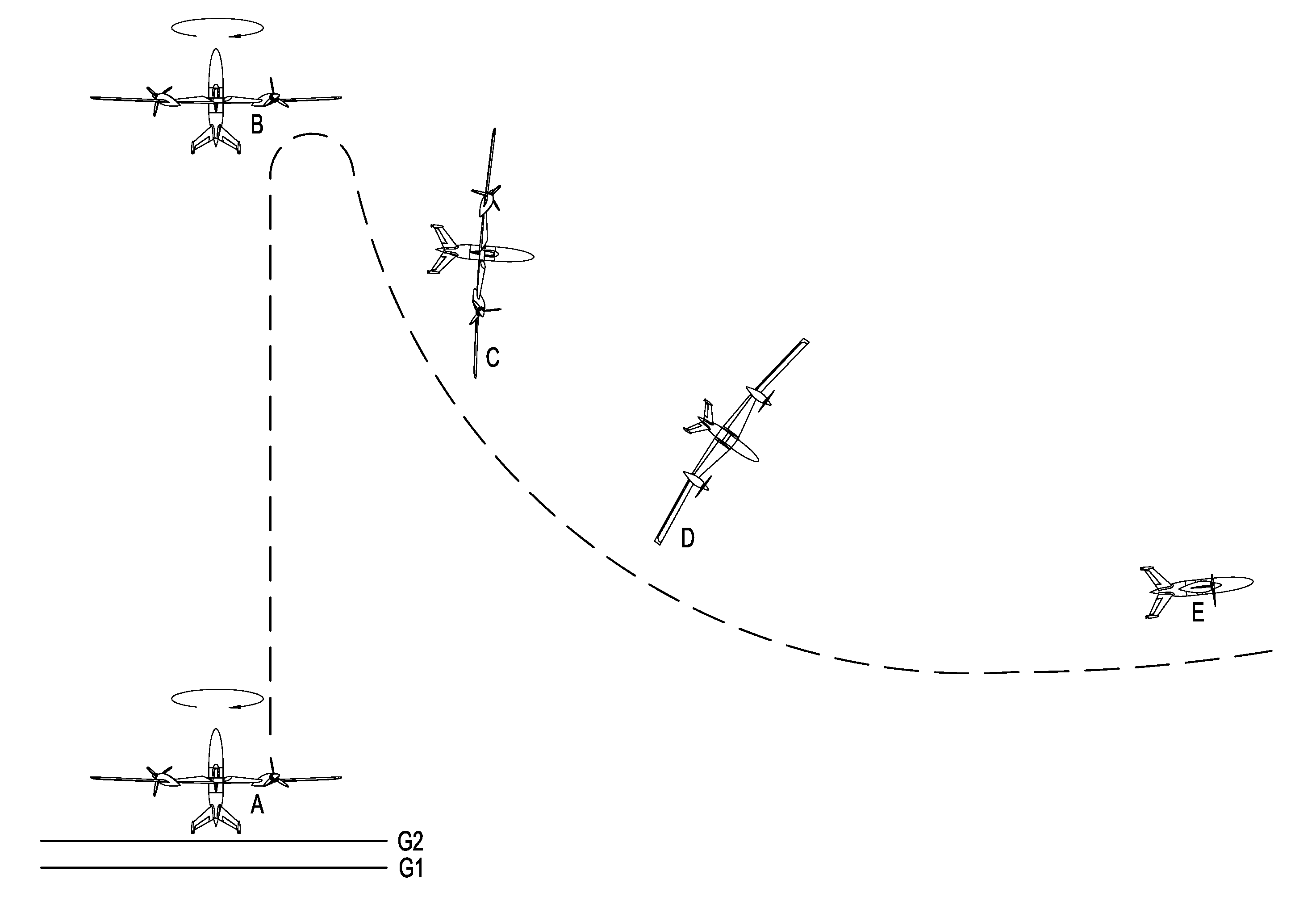
[0033]Embodiments of the invention can provide the features of both vertically flying, or hovering, aircraft and fixed wing aircraft. An aircraft that is changing altitude while traveling in a substantially vertical direction with the fuselage substantially perpendicular to the ground is defined to be in rotor flight mode. The same aircraft flying horizontally with the fuselage substantially parallel to the ground is defined as flying in a fixed wing flight mode. Some embodiments of the invention desirably result in increased efficiency and long range flight endurance.

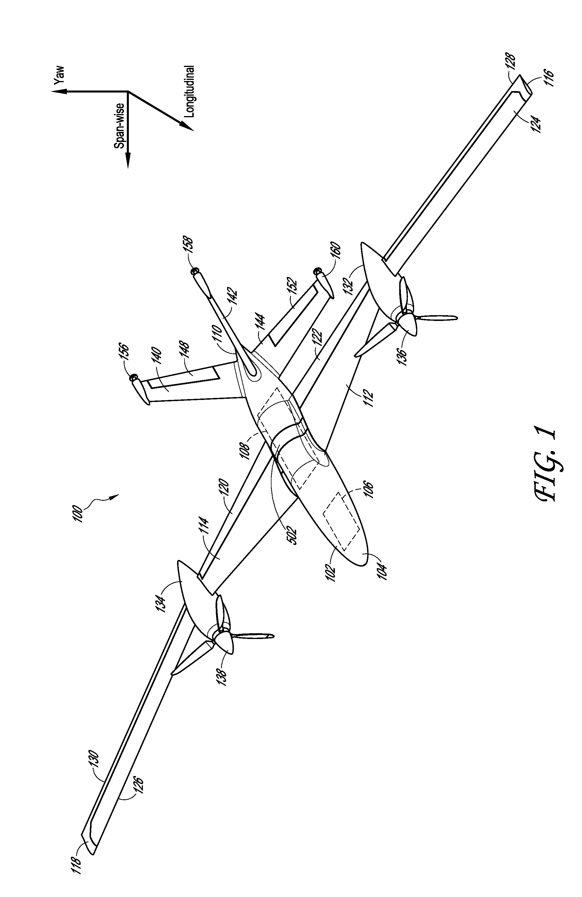
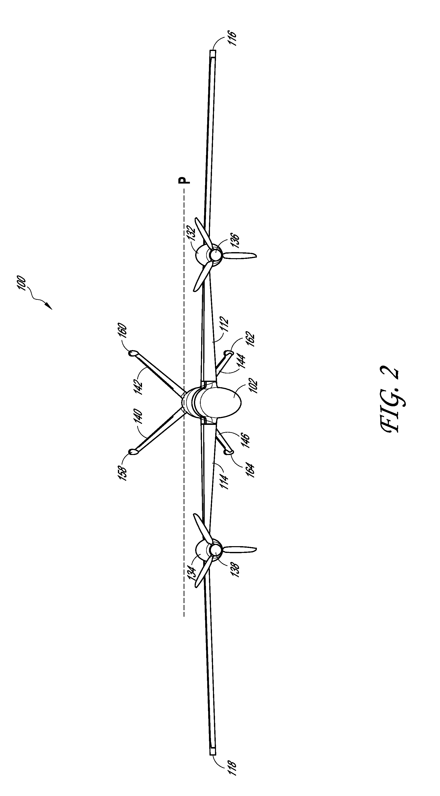
[0034]A preferred embodiment of the invention combines the wing function of a fixed wing aircraft and the rotor function similar to that provided by a traditional helicopter rotor. In a preferred embodiment, wh...


PUM


Abstract

An aircraft for use in fixed wing flight mode and rotor flight mode is provided. The aircraft can include a fuselage, wings, and a plurality of engines. The fuselage can comprise a wing attachment region further comprising a rotating support. A rotating section can comprise a rotating support and the wings, with a plurality of engines attached to the rotating section. In a rotor flight mode, the rotating section can rotate around a longitudinal axis of the fuselage providing lift for the aircraft similar to the rotor of a helicopter. In a fixed wing flight mode, the rotating section does not rotate around a longitudinal axis of the fuselage, providing lift for the aircraft similar to a conventional airplane. The same engines that provide torque to power the rotor in rotor flight mode also power the aircraft in fixed wing flight mode.

Description

CROSS-REFERENCE TO RELATED APPLICATIONS[0001]This application claims the benefit of U.S. Provisional Patent Application No. 61 / 465,760, entitled “RotorWing—A VTOL configuration which merges the wing, rotor, and propulsion system for efficient cruise as an airplane,” filed on Mar. 24, 2011.[0002]This application hereby incorporates by reference the above-identified provisional application it its entirety.BACKGROUND OF THE INVENTION[0003]1. Field of the Invention[0004]The invention relates generally to aircraft designs, and, more particularly, to unmanned aircraft designs that combine the features of fixed wing aircraft and vertical takeoff and landing (VTOL) aircraft.[0005]2. Description of the Related Art[0006]Tactical Unmanned Aerial Vehicles (UAVs) have revolutionized the way wars are fought and intelligence is gathered because of their low-cost, safety, and long endurance. However, one major limitation of current UAVs is the need for prepared launch and recovery sites with large ...

Claims


Application Information

Patent Timeline
IPC IPC(8): B64C27/24
CPCB64C29/02B64C39/024B64C2201/088B64C2201/108B64C2201/162B64C2201/165B64C2201/104B64U50/14B64U30/12B64U50/13B64U10/20B64U30/10B64U70/80
Inventor PAGE, MARK ALLANMCCUE, MATTHEW ROBERTGODLASKY, ROBERT ANTHONY
Owner DZYNE TECH
Why Eureka
Try Eureka