Displacement measurement method and displacement measurement device

a technology of displacement measurement and displacement measurement, which is applied in the direction of measurement devices, optical conversion of sensor output, instruments, etc., can solve the problems of difficult to reduce the size and inability to achieve accurate measurement, and achieve the effect of simple configuration, reduced size, and adjustment of optical resolution

Inactive Publication Date: 2012-10-04
TAIYO YUDEN KK
View PDF5 Cites 15 Cited by
  • Summary
  • Abstract
  • Description
  • Claims
  • Application Information

AI Technical Summary

Benefits of technology

[0025]According to the present invention, a displacement measurement method and a displacement measurement device that have a simple configuration allowing for reduction in size, that are not affected by inclination accuracy of the diffraction grating or by a diffraction grating being off-positioned in a surface direction, and that enable an adjustment of the optical resolution can be provided. Also, measurement of displacements at different positions and different detection sensitivities can be performed simultaneously or chronologically with a single light source.

Problems solved by technology

However, when the above-mentioned optical interferometer is used, the following problems are caused.
Even when an angle is off by as small as the order of 0.01 degree, or a position is off by as small as the submicron order, an accurate measurement may not be achieved.
(3) Because the optical interferometer must include a collimator lens, a combination of mirrors, and a splitter, it is difficult to reduce the size.

Method used


Image

  • Displacement measurement method and displacement measurement device
  • Displacement measurement method and displacement measurement device
  • Displacement measurement method and displacement measurement device

Examples


embodiment 1

[0045]Basic Configuration

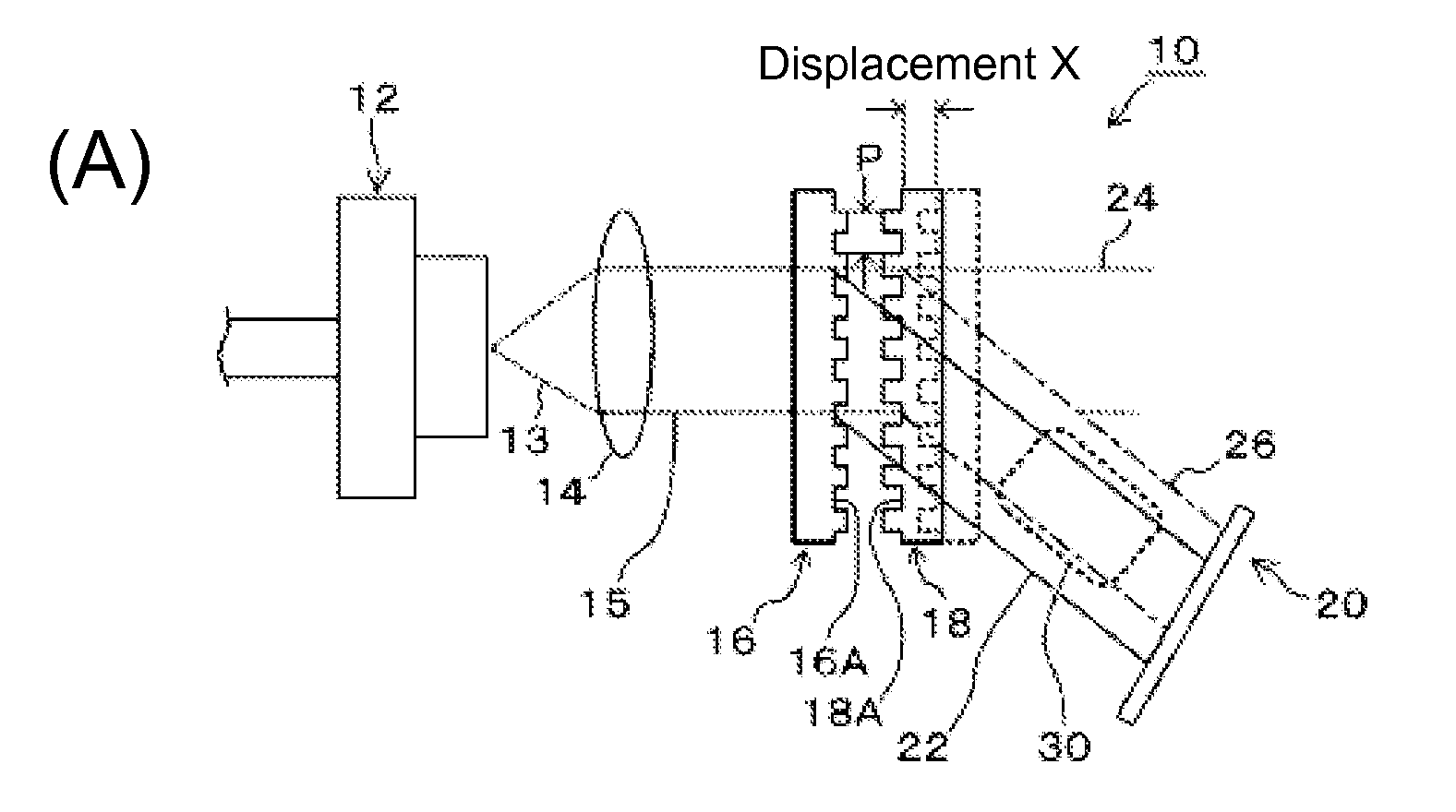
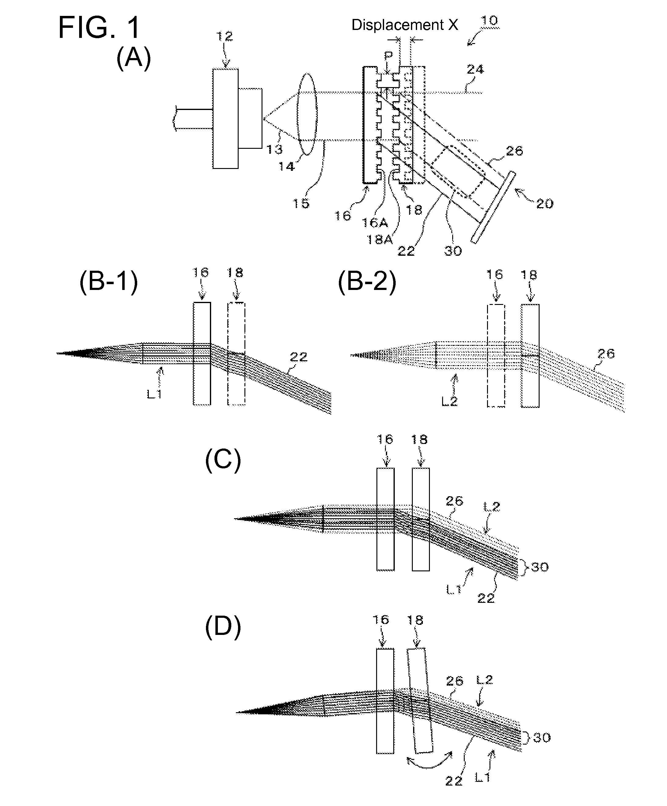
[0046]First, a basic configuration of the present invention will be explained with reference to FIG. 1. FIG. 1(A) is a diagram showing a basic configuration of this embodiment. FIGS. 1(B-1) and 1(B-2) are diagrams that respectively show an optical path 1 and an optical path 2. FIGS. 1(C) and 1(D) are diagrams showing interference between the optical paths 1 and 2. As shown in FIG. 1(A), a displacement measurement device 10 of this embodiment includes: a laser light source 12 such as a laser diode; a collimator lens 14 that turns a laser beam 13 from the laser light source 12 into parallel light 15 that travels straight; a first diffraction grating 16 on a stationary side; a second diffraction grating 18 on a moveable side that is disposed to so as to face and move relative to the first diffraction grating 16; and a first optical sensor 20 such as a photodiode. The parallel light 15 is divided into direct light 24 and diffracted light 22 when it passes throug...

application example

[0061]Next, an application example where the displacement measurement device 10 of this embodiment is used to measure a stretched amount of a brake wire of an electric assist bicycle will be explained with reference to FIGS. 4 to 8. FIG. 4 is a diagram showing an overall configuration of an electric assist bicycle. FIG. 5 is a diagram schematically showing a brake mechanism of the electric assist bicycle. FIG. 6 is a diagram showing a configuration example of a displacement measurement unit that is provided in the electric assist bicycle. FIG. 7(A) is a diagram showing a circuit configuration of a laser light source. FIG. 7(B) is a diagram showing a configuration of an optical detection circuit. FIG. 7(C) is a diagram showing a signal waveform of an output 1 from the optical detection circuit. FIG. 7(D) is a diagram showing measured characteristics of the displacement measurement unit of the displacement measurement unit. FIG. 8 shows relationships of a brake lever operation amount ...

embodiment 2

[0075]Next, Embodiment 2 of the present invention will be explained with reference to FIGS. 9 and 10. The same reference characters will be given to constituting elements that are the same as or corresponding to those in Embodiment 1 above (the same applies to other Embodiments that follow). FIG. 9(A) is a diagram showing a basic configuration of a displacement measurement device of this embodiment. FIG. 9(B) is a diagram showing a configuration of an optical detection circuit. FIG. 9(C) is a diagram showing a modification example of this embodiment. FIGS. 10(A) and 10(B) are diagrams showing signal waveforms of outputs A and B from the optical detection circuit. FIG. 10(C) is a signal waveform that indicates calculation results of the outputs A and B. This embodiment is an example of detecting phase difference by providing two optical areas with a phase difference. First, FIGS. 9(A) and 9(B) show an example of a case in which a step is provided to a diffraction grating on the movea...


PUM


Abstract

A displacement measurement device includes a first diffraction grating that generates first diffraction light of a prescribed order; a second diffraction grating movable relative to the first diffraction grating, the second diffraction grating dividing the zeroth-order light that has passed through the first diffraction grating into zeroth-order light and a second diffraction light of a prescribed order; and a first optical sensor that detects interfering light beams formed by the first diffraction light from the first diffraction grating and the second diffraction light from the second diffraction grating to determine an amount of a displacement of the second diffraction grating relative to the first diffraction grating.

Description

[0001]This application is a continuation of PCT International Application No. PCT / JP2010 / 067487 designating the United States, filed Oct. 5, 2010, which claims the benefit of Japanese Application No. 2009-231845, filed in Japan on Oct. 5, 2009, and Japanese Application No. 2010-084081, filed in Japan on Mar. 31, 2010. These applications are hereby incorporated by reference in their entireties.[0002]The present application also hereby incorporates by reference PCT International Application No. PCT / JP2010 / 066342, filed in Japan on Sep. 22, 2010, which claims the benefit of Japanese Application No. 2009-231908, filed in Japan on Oct. 5, 2009 in their entireties.TECHNICAL FIELD[0003]The present invention relates to a displacement measurement method and a displacement measurement device that utilize optical interference, and more particularly, to an expansion of a measuring range.BACKGROUND ART[0004]In recent years, from ecological and health standpoints, a bicycle equipped with an elect...

Claims


Application Information

Patent Timeline
Patent Type & Authority Applications(United States)
IPC IPC(8): G01B11/02
CPCG01D5/38B62M6/50
Inventor IKEDA, MASATOOYAMA, KATSUHIRO
Owner TAIYO YUDEN KK
Why Eureka
Try Eureka