System and Method for Signaling a Location of a Control Channel

a control channel and signaling system technology, applied in the field of digital communication, can solve the problems of proximity, high interference between user equipment and cellular system deployment, new challenges of hetnet deployment, etc., and achieve the effects of reducing computational overhead, reducing search time, and low overhead

Active Publication Date: 2012-10-04
FUTUREWEI TECH INC
View PDF9 Cites 35 Cited by
  • Summary
  • Abstract
  • Description
  • Claims
  • Application Information

AI Technical Summary

Benefits of technology

[0014]One advantage of an embodiment is that signaling of the location of a control channel helps a receiver by reducing the searching that the receiver may need to perform to find the control channel, thereby reducing computational overhead at the receiver.
[0015]A further advantage of an embodiment is that low overhead techniques are utilized to help reduce the signaling overhead, which may reduce the impact of the location signaling on the overall performance of the communications system.

Problems solved by technology

While such a deployment is optimal when the user density is uniform, in practice, it has serious shortcomings because the user density and traffic demand are rarely uniform.
HetNets present new challenges to the deployment of a cellular system.
In particular, the cellular layout may not be as regular as for a HomoNet since it is dependent on the hot spot locations.
The close proximity can create a high level of interference for both user equipment (UE) (also known as mobile station (MS), terminal, user, subscriber, wireless node, and the like) and BSs.
The interference can affect both the data channels and control channels.
While solutions exist to mitigate interference on the data channels, no such solution has been defined yet for the control channels.

Method used


Image

  • System and Method for Signaling a Location of a Control Channel
  • System and Method for Signaling a Location of a Control Channel
  • System and Method for Signaling a Location of a Control Channel

Examples


Embodiment Construction

[0038]The operating of the current example embodiments and the structure thereof are discussed in detail below. It should be appreciated, however, that the present disclosure provides many applicable inventive concepts that can be embodied in a wide variety of specific contexts. The specific embodiments discussed are merely illustrative of specific structures of the disclosure and ways to operate the disclosure, and do not limit the scope of the disclosure.

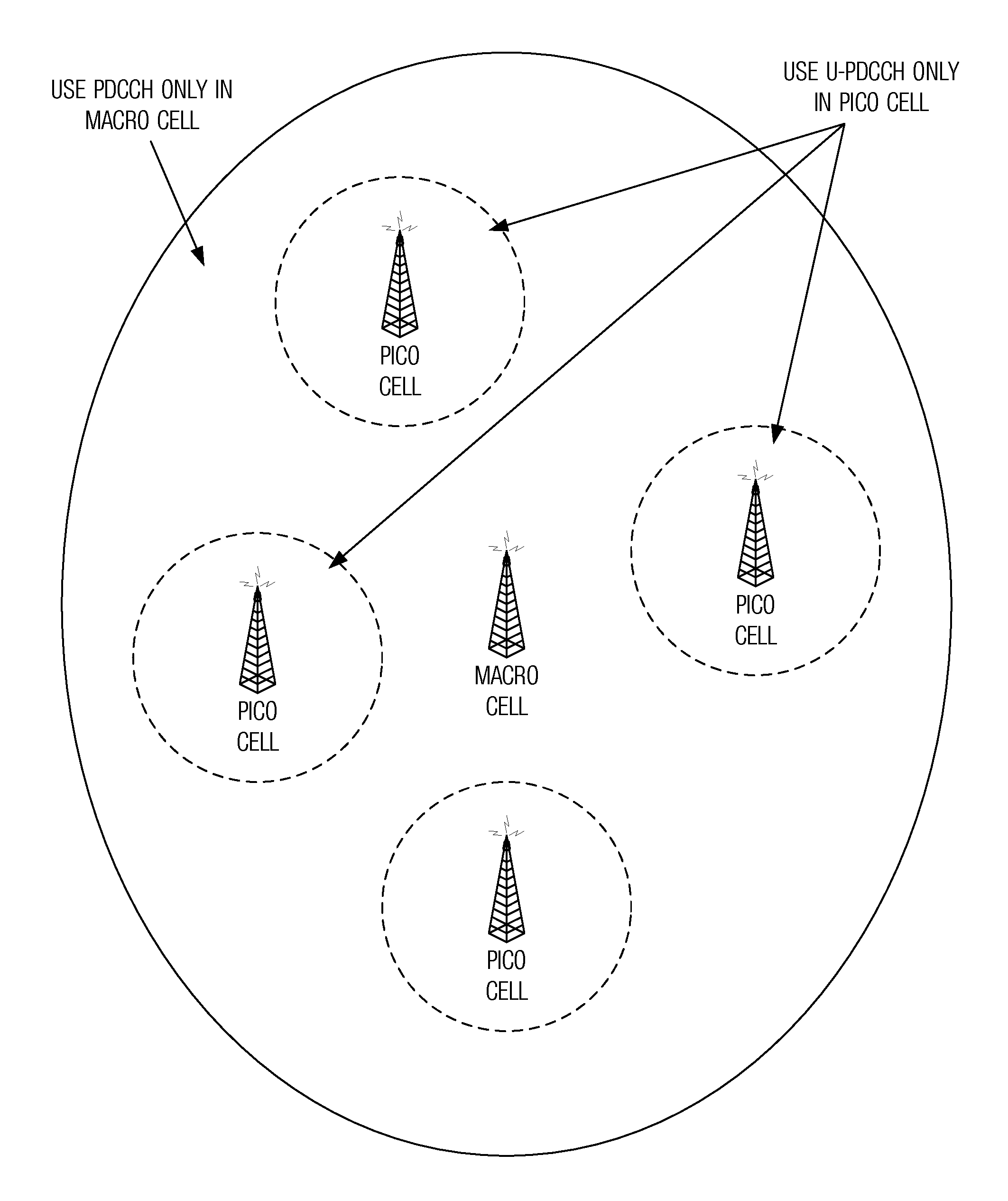
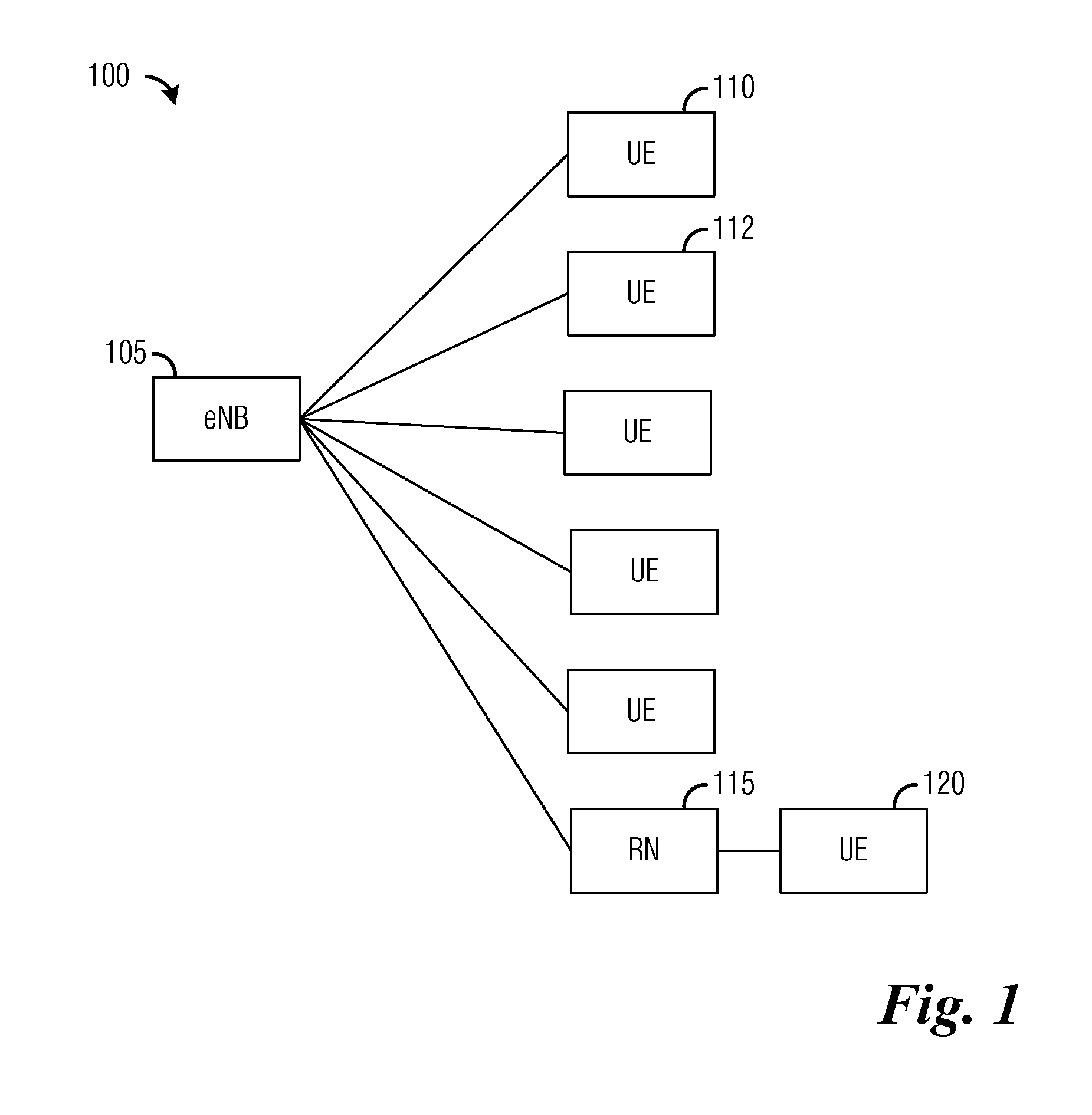
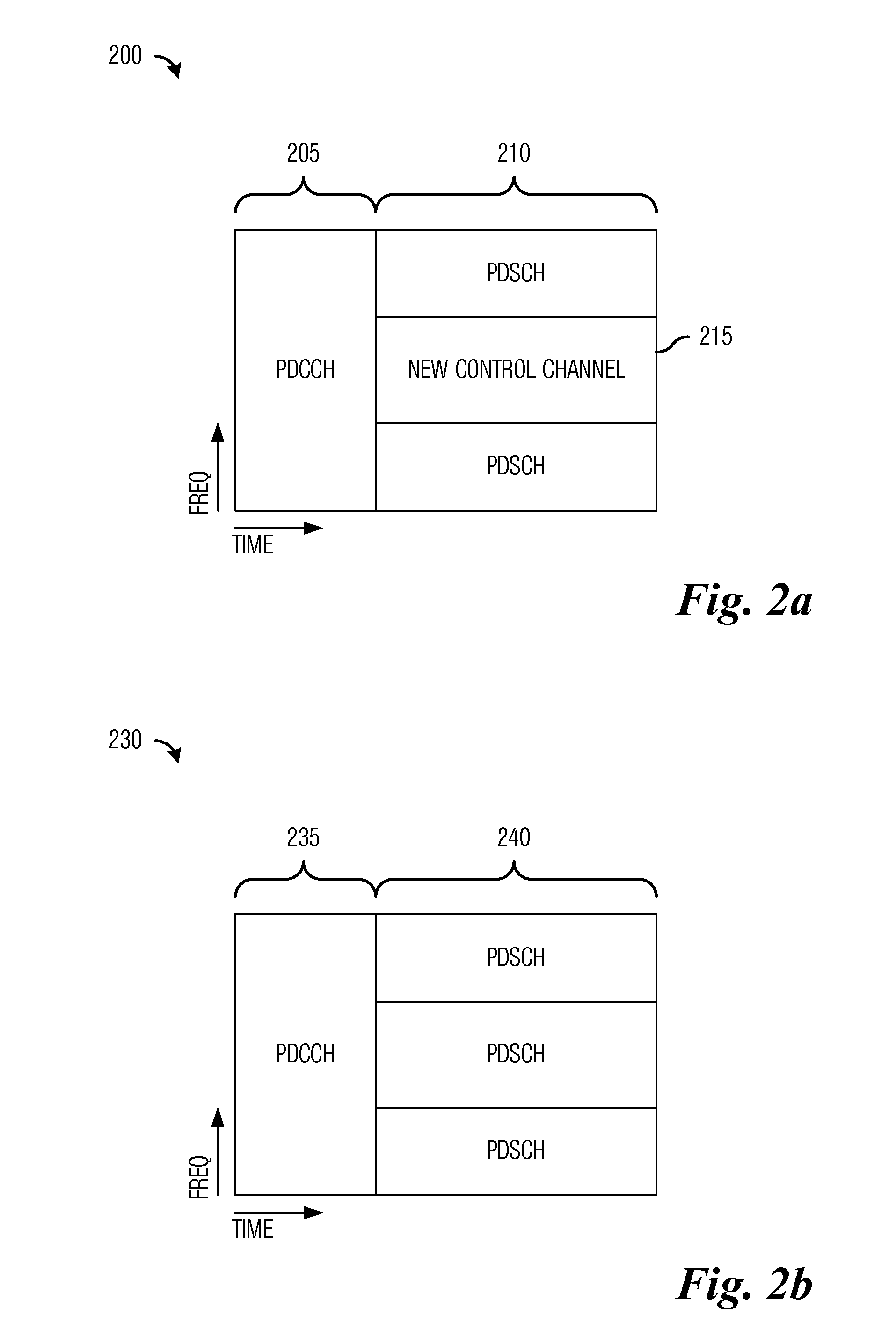
[0039]One embodiment of the disclosure relates to signaling a location of a control channel. For example, an eNB generates a location indicator that identifies a location of a control channel located in a data region of a subframe and transmits the location indicator to a wireless node. For example, a wireless node receives a location indicator that identifies a location of a control channel in a data region of a subframe and searches for control information in the control channel according to the location indicator.

[0040]The pres...


PUM


Abstract

A method for transmitting control information to a wireless node in a communications system includes mapping, by a communications controller, the control information onto resources associated with a wireless node specific search space, the wireless node specific search space being located in a first data region of a first subframe, the first subframe including a first common search space in addition to the wireless node specific search space. The method also includes generating, by the communications controller, a location indicator identifying a location of the wireless node specific search space. The method further includes transmitting, by the communications controller, the first subframe to the wireless node, and transmitting, by the communications controller, the location indicator to the wireless node.

Description

[0001]This application claims the benefit of U.S. Provisional Applications: No. 61 / 471,049, filed on Apr. 1, 2011, entitled “System and Method for Signaling a Location of a Control Channel,” No. 61 / 470,940, filed on Apr. 1, 2011, entitled “System and Method for Transmission and Reception of Control Channels in a Communications System,” No. 61 / 471,055, filed on Apr. 1, 2011, entitled “System and Method for Transmission and Reception of Control Channels,” and No. 61 / 471,061, filed on Apr. 1, 2011, entitled “System and Method for Transmission and Reception of Control Channels,” which applications are hereby incorporated herein by reference.CROSS-REFERENCE TO RELATED APPLICATIONS[0002]This application is related to the following co-assigned patent applications: Ser. No. 13 / 434,449, filed Mar. 29, 2012, Attorney Docket Number HW 83138110US05, entitled “System and Method for Transmission and Reception of Control Channels in a Communications System”; Ser. No. XX / XXX,XXX, filed Mar. 30, 201...

Claims


Application Information

Patent Timeline
Patent Type & Authority Applications(United States)
IPC IPC(8): H04W72/04
CPCH04W48/12H04W24/10H04W72/23H04W72/20
Inventor SARTORI, PHILIPPEQU, BINGYUXIAO, WEIMINCLASSON, BRIANDESAI, VIPUL
Owner FUTUREWEI TECH INC
Why Eureka
Try Eureka