Grid Event Detection

a technology of grid events and event detection, applied in the field of grid event detection, can solve the problems of significant loss of revenue for service providers

Active Publication Date: 2012-10-04
LANDISGYR TECH
View PDF15 Cites 216 Cited by
  • Summary
  • Abstract
  • Description
  • Claims
  • Application Information

AI Technical Summary

Benefits of technology

[0013]Particular embodiments of the subject matter described in this specification can be implemented so as to realize one or more of the following advantages. A data processing apparatus can be configured to determine that a grid event exists and a location of a network element that is causing the grid event. The time required to determine that a grid event has occurred and / or the source of the grid event can be reduced by using characteristics of continually monitored communications signals to determine the existence of a grid event. The location of the network element that is causing the grid event can be determined using map data so that service personnel can be dispatched.

Problems solved by technology

These service providers are dependent on proper operation of their respective networks to deliver services to the customers because operational problems in the network can result in lost revenue for the service provider.
For example, the service provider may lose revenue based on an inability to provide service during a network outage.
While a service provider can remedy network outages and other network problems by accessing endpoints in the network and / or dispatching workers, the time and resources required to identify the cause of the outage or problem can result in significant loss of revenue for the service provider.

Method used


Image

  • Grid Event Detection
  • Grid Event Detection
  • Grid Event Detection

Examples


Embodiment Construction

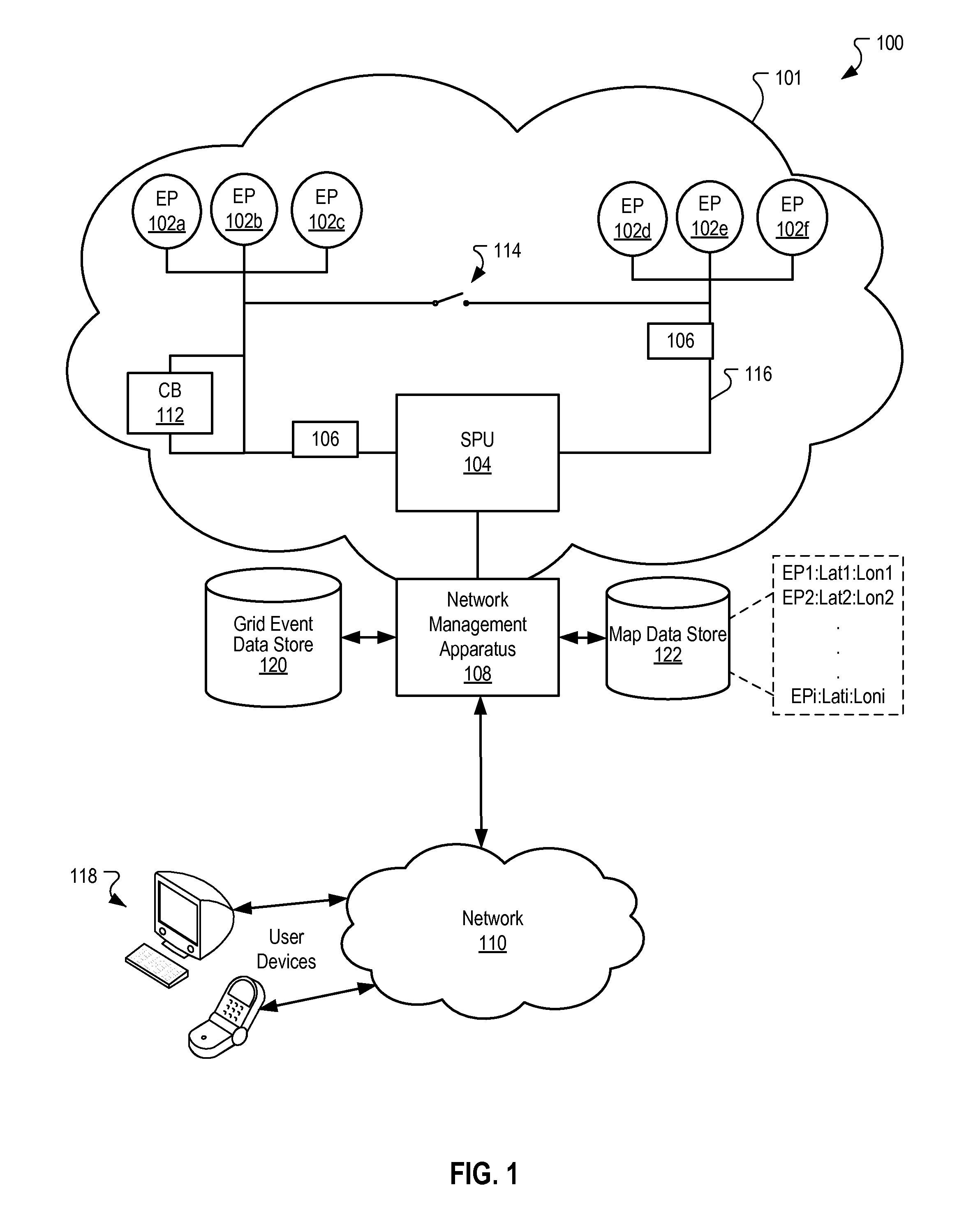
[0022]FIG. 1 is a block diagram of an example network environment 100 in which endpoints transmit data. The network environment 100 includes a service network 101 in which a plurality of endpoints 102a-102f (collectively referred to as endpoints 102) are coupled (e.g., communicatively coupled) to a substation processing unit 104. The endpoints 102 are network elements of the network 101 and can be any device capable of transmitting data in the network environment 100. For example, the endpoints 102 can be meters or other elements of a utility network, computing devices, television set top terminals, or telephones that transmit data in the service network. The description that follows refers to the endpoints 102 as power meters in a power distribution network. However, the description that follows is applicable to other types of endpoints 102 in utility networks or other networks. For example, the description that follows is applicable to gas meters and water meters that are respecti...


PUM


Abstract

Methods, systems, and apparatus, including computer programs encoded on a computer storage medium, for detecting grid events. In one aspect, a method includes receiving signal characteristic data that specify signal characteristic values for signals that are received over each of a plurality of communications channels of a power line communications network. A determination is made that the signal characteristic values for the signals that are received over at least one of the communications channels are outside of a baseline signal value range. An endpoint that communicates over the at least one communications channel is identified, and a determination is made that a set of the signal characteristic values for the identified endpoint matches one of a plurality a grid event signatures for the identified endpoint. Data that identify the endpoint and a particular grid event that is represented by the matched grid event signature are provided.

Description

BACKGROUND[0001]This specification relates to detecting grid events.[0002]Service providers utilize distributed networks to provide services to customers over large geographic areas. For example, communications companies utilize a distributed communications network to provide communications services to customers. Similarly, power companies utilize a network of power lines and meters to provide power to customers throughout a geographic region.[0003]These service providers are dependent on proper operation of their respective networks to deliver services to the customers because operational problems in the network can result in lost revenue for the service provider. For example, the service provider may lose revenue based on an inability to provide service during a network outage. Therefore, when a network outage or other network event that disrupts service occurs, it is in the best interest of the service provider to identify the cause of the problem and correct the problem as soon ...

Claims


Application Information

Patent Timeline
Patent Type & Authority Applications(United States)
IPC IPC(8): H04B3/46
CPCH04L43/04Y02E60/7823Y02E60/7815H02J13/002Y02E60/7892Y04S40/121H04B3/542H02J13/0024Y04S40/146H04B2203/5458H04B2203/5408Y04S40/122H02J13/00009H02J13/00007H02J13/00034Y02E60/00
Inventor MCHANN, JR., STANLEY E.
Owner LANDISGYR TECH
Why Eureka
Try Eureka