Method and System for Determining Projections in Non-Central Catadioptric Optical Systems

a catadioptric optical system and projection technology, applied in image analysis, instruments, computing, etc., can solve problems such as incorrect solutions, skewed 3d estimation, and no analytical solution for general non-central catadioptric systems

Inactive Publication Date: 2012-10-04
MITSUBISHI ELECTRIC RES LAB INC
View PDF0 Cites 4 Cited by
  • Summary
  • Abstract
  • Description
  • Claims
  • Application Information

AI Technical Summary

Benefits of technology

[0018]One embodiment is based on another realization, that if a reflector of the catadioptric systems is rotationally symmetric, entire coordinate system can be rotated to position the COP on at least one axis. This realization enables the embodiment to reduce a degree of a forward projection equation (FPE) in one unknown, wherein the unknown is a coordinate of the reflection point. For example, one embodiment determines and solves the FPE of eights degrees.

Problems solved by technology

However, there is no analytical solution of projection for general non-central catadioptric systems, when a camera is placed at an arbitrary position with respect to a reflector or a refractor.
However, those methods lead to inaccuracies such as skewed 3D estimation.
However, those methods are time-consuming and inappropriate initialization leads to incorrect solutions.

Method used


Image

  • Method and System for Determining Projections in Non-Central Catadioptric Optical Systems
  • Method and System for Determining Projections in Non-Central Catadioptric Optical Systems
  • Method and System for Determining Projections in Non-Central Catadioptric Optical Systems

Examples


Embodiment Construction

[0029]Method and System Overview

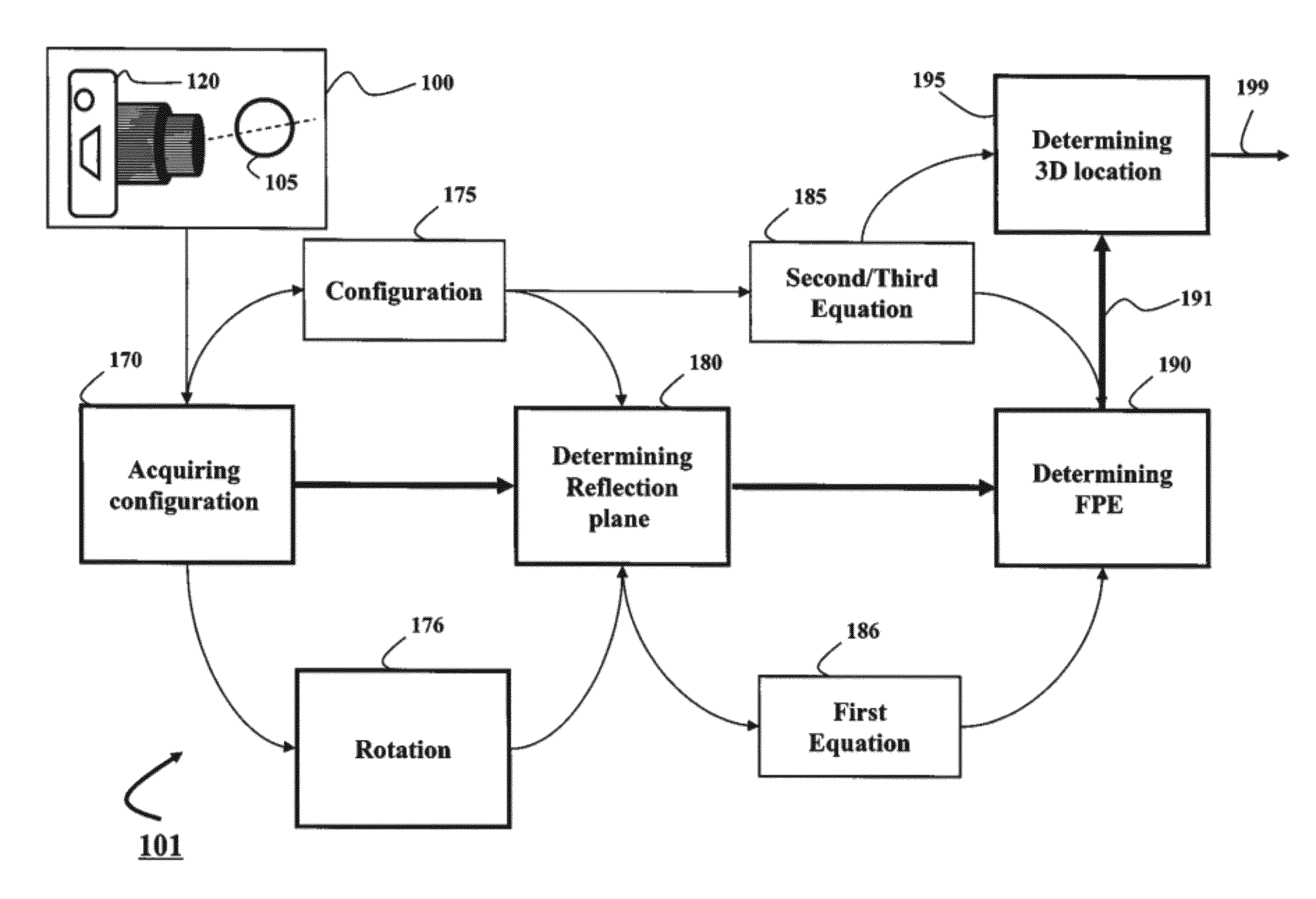
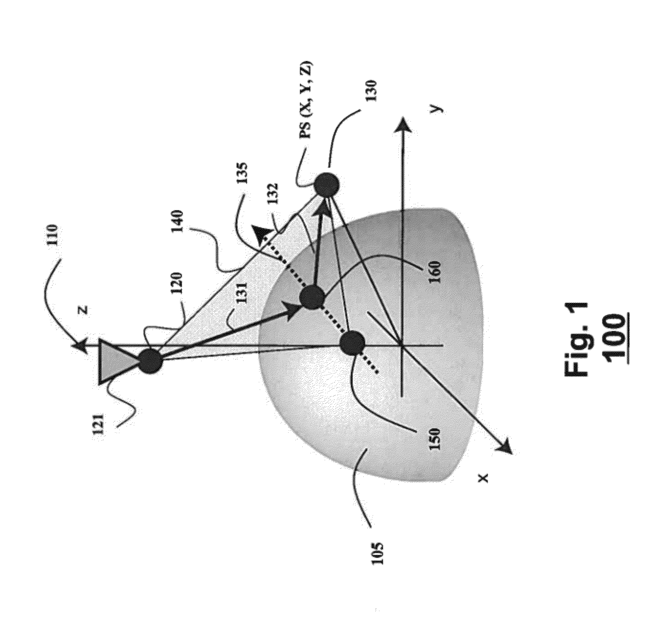
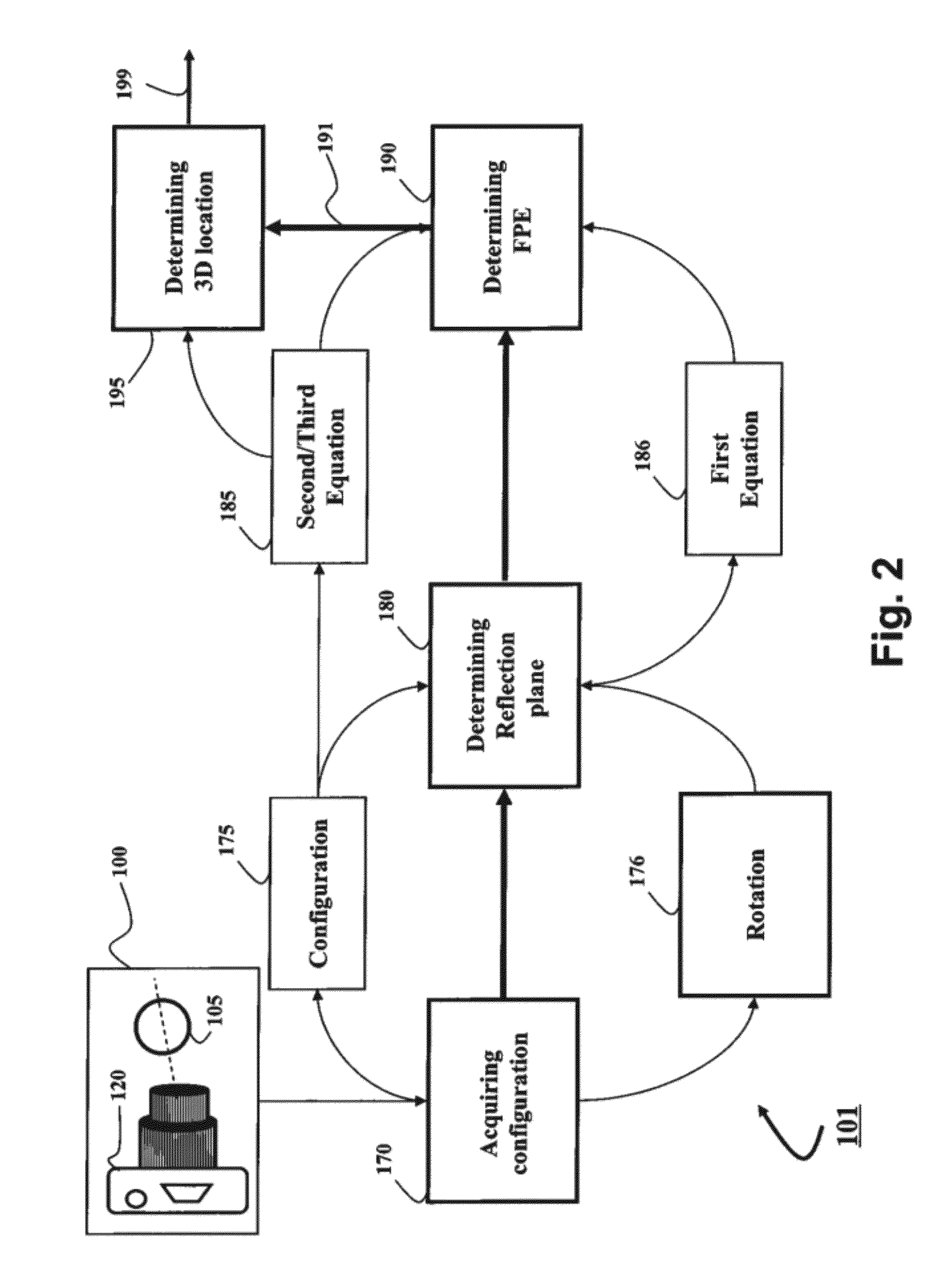
[0030]Embodiments of invention are based on a realization that a three-dimensional (3D) location of a reflection point of a ray between a point in a scene (PS) and a center of projection (COP) of a camera of a catadioptric system can be determined analytically using mapping a 3D structure of the catadioptric system on a two-dimensional (2D) plane defined by the COP, the PS, and a point of intersection of a normal of a reflection point with an axis of symmetry of a reflector of the catadioptric system.

[0031]Such configurations include non-central catadioptric systems having a camera arranged at a distance from a surface of the reflector, wherein the surface is quadric and rotationally symmetric around an axis of symmetry. Importantly, for some embodiments, there is no restriction on a position of a center of projection (COP) of the camera used in the catadioptric system. For example, the COP can be arranged outside of the axis of symmetry.

[0032]FIG. 1 ...


PUM


Abstract

A three-dimensional (3D) location of a reflection point of a ray between a point in a scene (PS) and a center of projection (COP) of a camera of a catadioptric system is determined. The catadioptric system is non-central and includes the camera and a reflector, wherein a surface of the reflector is a quadric surface rotationally symmetric around an axis of symmetry. The 3D location of the reflection point is determined based on a law of reflection, an equation of the reflector, and an equation describing a reflection plane defined by the COP, the PS, and a point of intersection of a normal to the reflector at the reflection point with the axis of symmetry.

Description

FIELD OF THE INVENTION[0001]This invention relates generally to catadioptric optical systems, and more particularly to determining a projection in non-central catadioptric optical systems.BACKGROUND OF THE INVENTION[0002]A catadioptric optical system combines refraction and reflection principles, usually via lenses (dioptrics) and curved mirrors (catoptrics). The catadioptric system includes camera imaging reflectors or refractors, enabling wide field-of-view (FOV) imaging. The catadioptric systems have been used in a wide range of applications, including panoramic imaging and visualization, wide-angle reconstruction, surveillance, and mobile robot and car navigation. The catadioptric system can be central or non-central.[0003]Central Catadioptric System[0004]Central catadioptric systems use a camera-mirror pair arranged to enable an effective single viewpoint, i.e., all rays of light forming an image acquired by the camera sensor intersect at one point. Examples of the central cata...

Claims


Application Information

Patent Timeline
Patent Type & Authority Applications(United States)
IPC IPC(8): G06K9/00
CPCG06T7/0055G02B17/08G06T7/514
Inventor AGRAWAL, AMIT K.TAGUCHI, YUICHIRAMALINGAM, SRIKUMAR
Owner MITSUBISHI ELECTRIC RES LAB INC
Why Eureka
Try Eureka