
Force measurement for large bend angles of catheter

a force measurement and catheter technology, applied in the field of invasive medical devices, can solve the problems of extreme or large bend angles at the distal end of the device, no known device or method for accurately sensing, and unfavorable damage to the heart tissue and even perforation of the heart wall

Active Publication Date: 2012-10-04
BIOSENSE WEBSTER (ISRAEL) LTD
View PDF9 Cites 50 Cited by
  • Summary
  • Abstract
  • Description
  • Claims
  • Application Information

AI Technical Summary

Problems solved by technology

Excessive pressure, however, may cause undesired damage to the heart tissue and even perforation of the heart wall.
To date, there have been no known devices or methods for accurately sensing displacement of a joint in a device, such as a catheter, and for measuring force exerted on the distal end or tip of the device, particularly force resulting in extreme or large bend angles at the distal end of the device.

Method used


Image

  • Force measurement for large bend angles of catheter
  • Force measurement for large bend angles of catheter
  • Force measurement for large bend angles of catheter

Examples


Embodiment Construction

[0017]This application uses the technical disclosure of commonly owned pending U.S. patent application Ser. No. 11 / 868,733, filed Oct. 8, 2007, and U.S. patent application Ser. No. 12 / 327,226, filed Dec. 3, 2008 which are assigned to the assignee of the present patent application and whose disclosure of both references is incorporated herein by reference. Accordingly, like or similar features are identified using the same reference numerals from U.S. patent application Ser. No. 12 / 327,226.

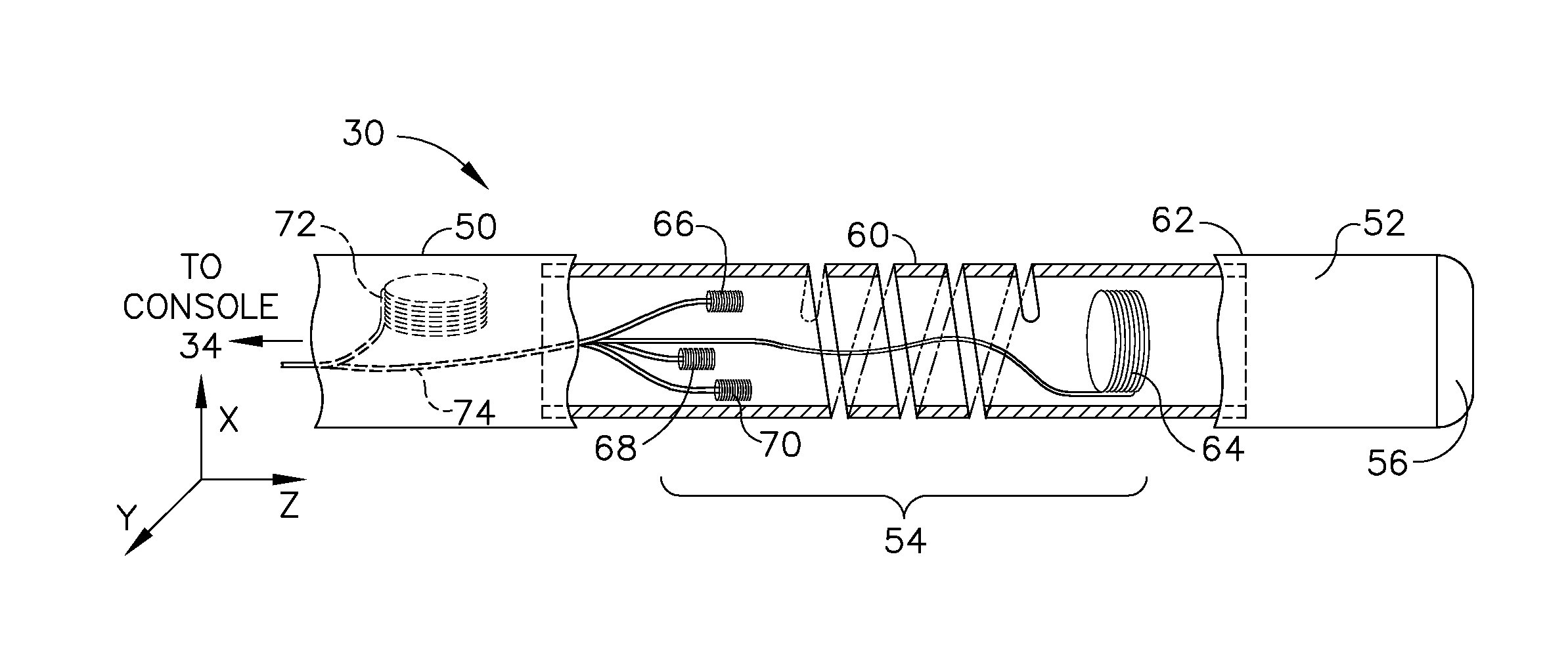
[0018]The above-mentioned U.S. patent application Ser. No. 11 / 868,733 describes a catheter whose distal tip is coupled to the distal end of the catheter insertion tube by a spring-loaded joint, which deforms in response to pressure exerted on the distal tip when it engages tissue. A magnetic position sensing assembly within the probe, comprising coils on opposite sides of the joint, senses the position of the distal tip relative to the distal end of the insertion tube. Changes in this relative posi...


PUM


Abstract

A method for calibrating a force measuring probe comprises providing a probe having an insertion tube with a distal tip, a joint comprising a resilient member, a joint sensor in conjunction with a processor coupled to the probe wherein the processor has a memory of an axial displacement threshold for the joint stored therein; applying force to the distal tip; measuring the displacement and deflection of the distal tip; correlating the measured displacement and deflection of the distal tip to the applied force and storing the correlation in the memory until reaching the axial displacement threshold; applying force greater than the axial displacement threshold to the distal tip to define a new force value; measuring the position of the distal tip in a plane transverse to the direction of force exerted on the distal tip; correlating the measured position of the distal tip in the plane transverse to the direction of force to the new force value and storing the correlation in the memory until reaching a pre-established upper limit for the new force value.

Description

FIELD OF THE INVENTION[0001]The present invention relates generally to invasive medical devices, and specifically to methods and devices for sensing displacement of a joint in a probe, such as a catheter, that is applied to the body of a patient, and for measuring force exerted on the distal end or tip of the catheter, particularly force resulting in extreme or large bend angles at the catheter distal end.BACKGROUND OF THE INVENTION[0002]In some diagnostic and therapeutic techniques, a catheter is inserted into a chamber of the heart and brought into contact with the inner heart wall. In such procedures, it is generally important that the distal tip of the catheter engages the endocardium with sufficient pressure to ensure good contact. Excessive pressure, however, may cause undesired damage to the heart tissue and even perforation of the heart wall.[0003]For example, in intracardiac radio-frequency (RF) ablation, a catheter having an electrode at its distal tip is inserted through ...

Claims


Application Information

Patent Timeline
Patent Type & Authority Applications(United States)
IPC IPC(8): A61B5/055
CPCA61B5/06A61B5/6885A61B2019/5251A61N1/056A61B2019/465A61B18/1492A61B2090/065A61B2034/2051A61B5/062
Inventor BONYAK, YEVGENYLUDWIN, DORON
Owner BIOSENSE WEBSTER (ISRAEL) LTD
Features
  • Generate Ideas
  • Intellectual Property
  • Life Sciences
  • Materials
  • Tech Scout
  • Unparalleled Data Quality
  • Higher Quality Content
  • 60% Fewer Hallucinations
Learn More