Robot control method and robot
- Summary
- Abstract
- Description
- Claims
- Application Information
AI Technical Summary
Benefits of technology
Problems solved by technology
Method used
Image

Examples
first embodiment
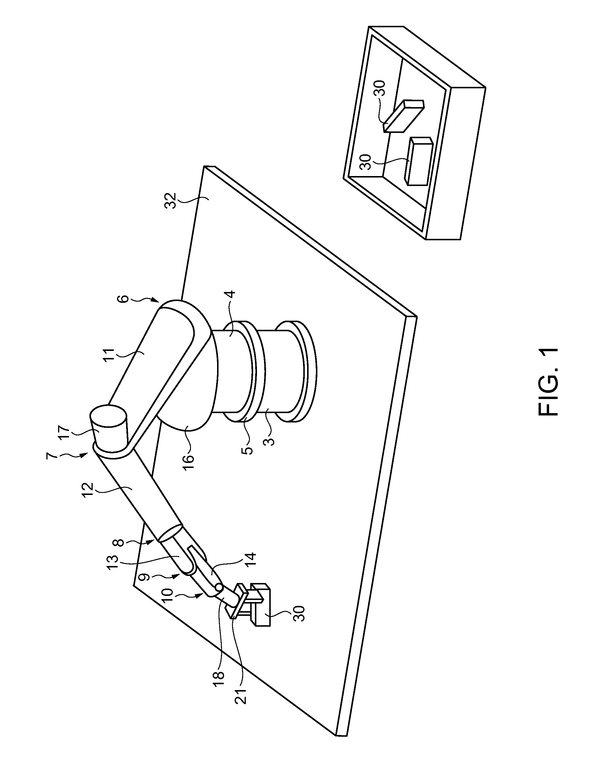
[0056]FIG. 1 is a perspective view illustrating the outlines of a robot 1 which is used in a first embodiment and each embodiment which will be described later and an operation which is performed by the robot 1. Meanwhile, in the drawing, a control apparatus which controls the robot 1 is not shown.
[0057]As shown in the drawing, the robot 1 includes an upper pedestal 4, a lower pedestal 3, a plurality of arms, and motors which drive the corresponding arms. The upper pedestal 4 is provided on the lower pedestal 3 and is rotated at a rotation position 5 by driving a motor (not shown). A first arm 11 is installed on the upper pedestal 4, and is rotated at a rotation position 6 by driving a motor 16. A second arm 12 is connected to the first arm 11, and is rotated at a rotation position 7 by driving a motor 17. A third arm 13 is connected to the second arm 12 and is rotated at a rotation position 8 by driving a motor (not shown). A fourth arm 14 is installed on the third arm 13 and ...
second embodiment
[0087]Next, a second embodiment of the invention will be described. FIG. 9 is a flowchart illustrating a robot control method according to the second embodiment. Further, FIGS. 10A to 10H are process charts illustrating the robot control method according to the second embodiment. The robot control method according to the second embodiment is similar to the robot control method according to the above-described first embodiment. The configurations of the work 30 which is a target and the robot 1 which is used to deliver the corresponding work are approximately the same. The difference therebetween is a configuration that a contact sensor 31 is added to the first hand unit 21. Here, description is made while drawings corresponding to the above-described FIGS. 1 to 4C, 7, and 8 are omitted and only the flowchart and process charts are used. Like the above-described FIGS. 6A to 6F, FIGS. 10A, 10C, 10E, and 10G are drawings in which the work 30 is viewed from the X direction, and FIGS. 10...
third embodiment
[0097]Next, a third embodiment of the invention is described. FIG. 11 is a flowchart illustrating a robot control method according to the third embodiment. Further, FIGS. 12A to 12F are process charts illustrating the robot control method according to the third embodiment. The robot control method according to the third embodiment is similar to the robot control method according to the above-described first embodiment. The configurations of the work 30 which becomes a target and the robot 1 which is used to deliver the corresponding work are approximately the same. Here, like the second embodiment, description will be made using only a flowchart and process charts.
[0098]Like the above-described FIGS. 6A to 6F and FIGS. 10A to 10G, FIGS. 12A, 12C, and 12E are drawings in which the work 30 is viewed from the X direction, and FIGS. 12B, 12D, and 12F are drawings in which the work 30 is viewed from the Y direction. Further, the finger units 27 are hatched in FIGS. 12B, 12D, and 12F. Fur...
PUM
 Abstract
Description
Claims
Application Information
 - Generate Ideas
- Intellectual Property
- Life Sciences
- Materials
- Tech Scout
- Unparalleled Data Quality
- Higher Quality Content
- 60% Fewer Hallucinations
Browse by: Latest US Patents, China's latest patents, Technical Efficacy Thesaurus, Application Domain, Technology Topic, Popular Technical Reports.
© 2025 PatSnap. All rights reserved.Legal|Privacy policy|Modern Slavery Act Transparency Statement|Sitemap|About US| Contact US: help@patsnap.com