

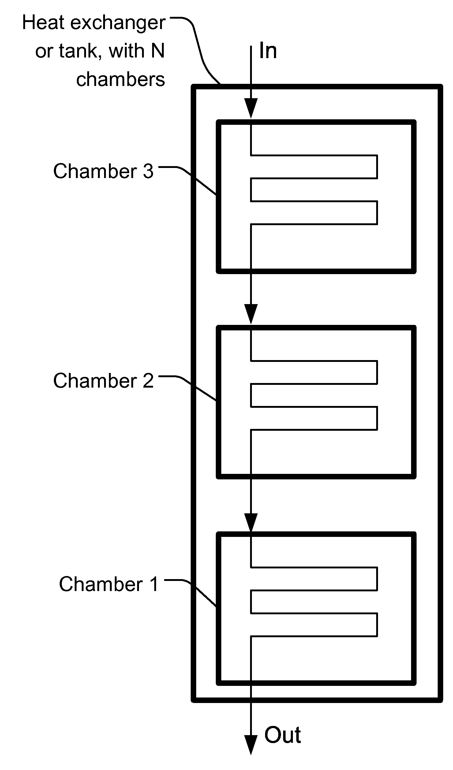
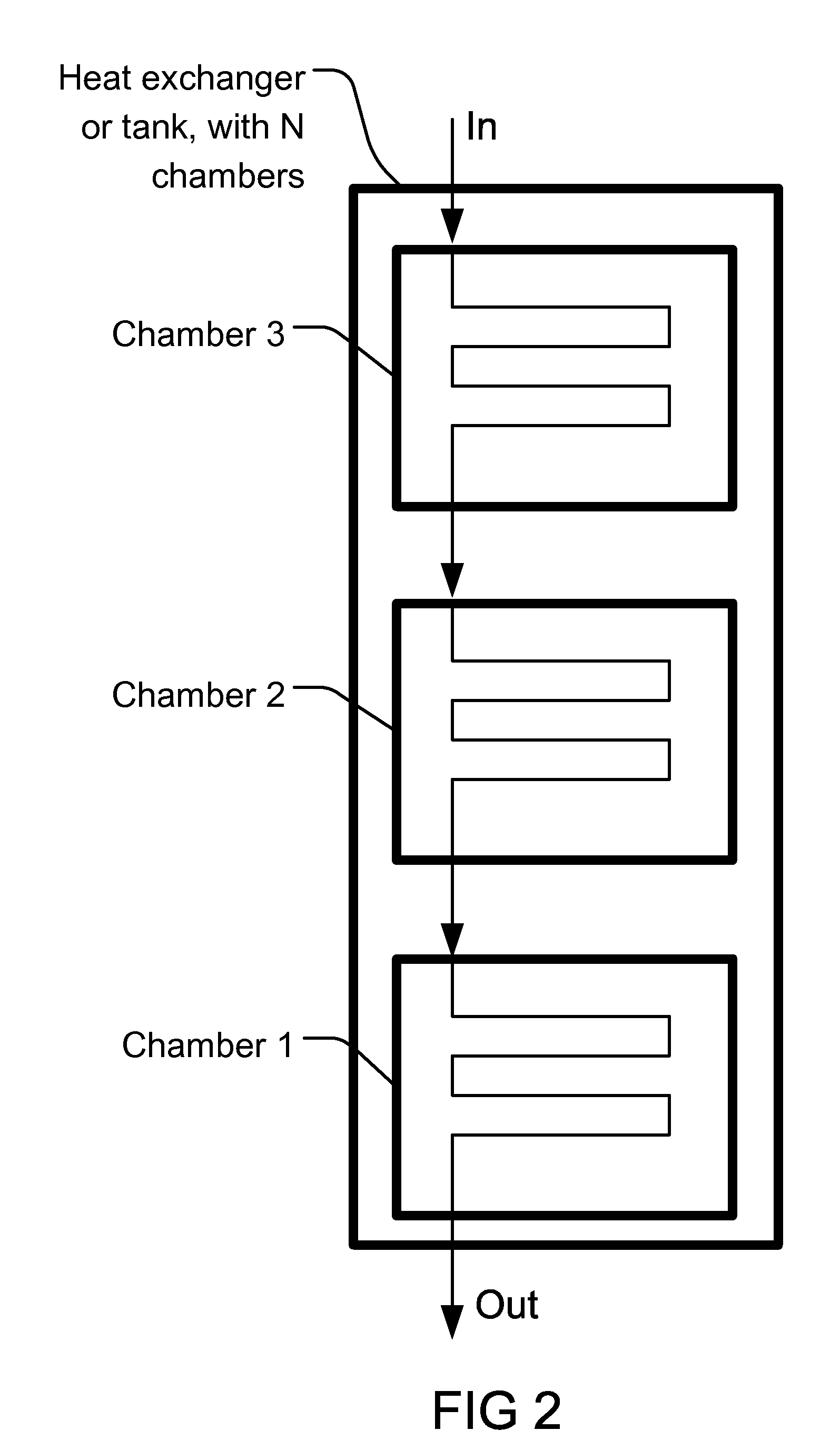
Heat Exchange Using Underground Water System
a technology of underground water and heat exchange, which is applied in indirect heat exchangers, lighting and heating apparatus, greenhouse gas reduction, etc., can solve the problem of low efficiency of conventional heat pumps in extreme hot and cold weather
- Summary
- Abstract
- Description
- Claims
- Application Information
AI Technical Summary
Problems solved by technology
Method used
Image

Examples
Embodiment Construction
[0234]Here are some of the embodiments / examples of the current invention:
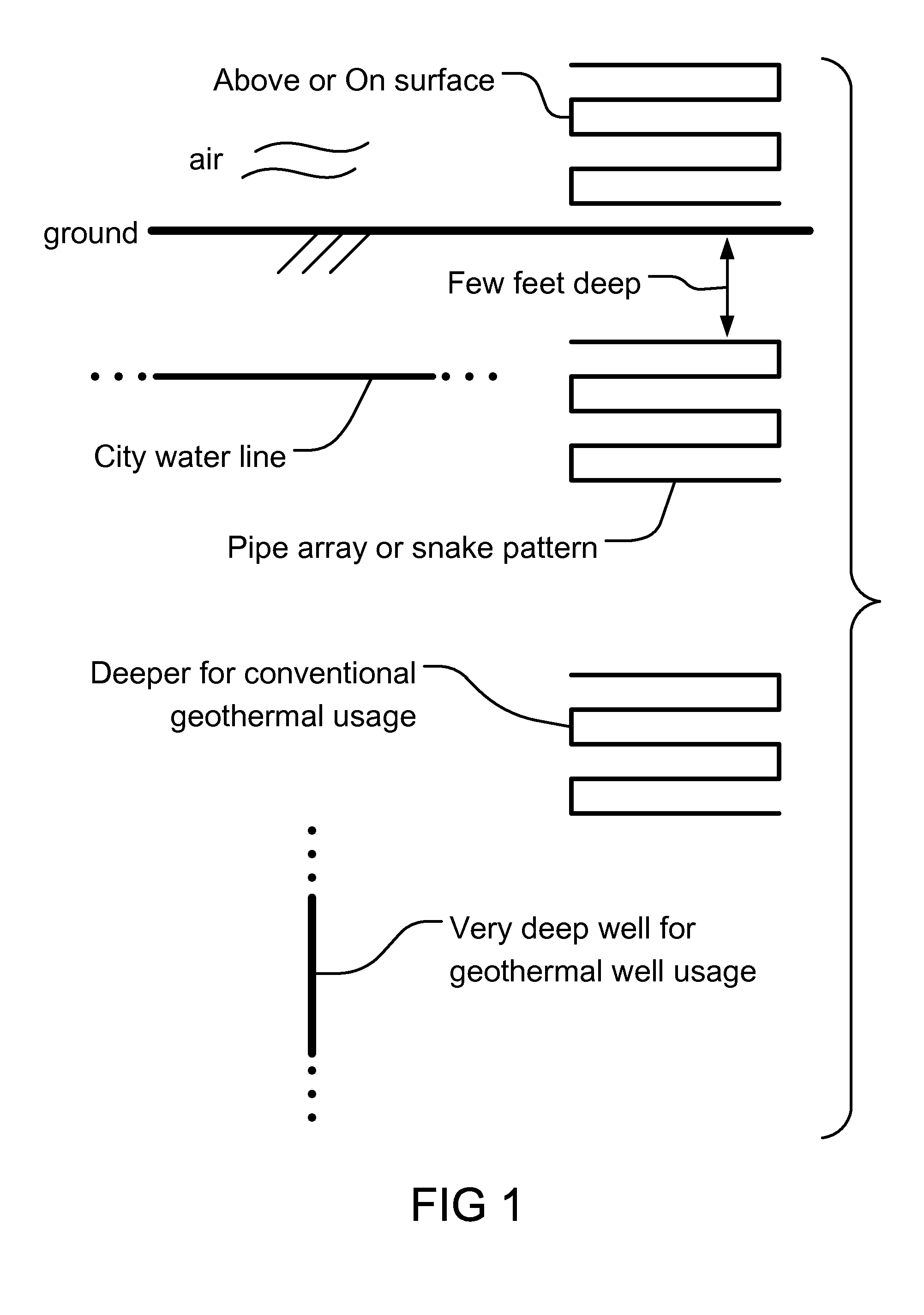
[0235]The source of the energy can be from the following sources, or through the following medium or phenomenon: dry steam hydrothermal, hot water hydrothermal, hot dry rock, geopressurized geothermal, magma, volcanic lava, activities, or chambers, hot springs, springs, water fountains, undercurrent rivers in ocean, underground water basins, rivers, or currents, high pressure steam or gasses trapped underground or in Earth cavities, cavities caused by oil, gas, or mineral explorations or mining, caverns or caves, cavities under rivers, ground, or seas, natural or human-made tunnels, gaps or structures caused by earthquakes on the surface or depth of the planet Earth, geysers (such as that in Yellowstone Park in US), waterfalls, rivers, wind, surface or ground water supplies, man-made water containers or reservoirs, flood-prevention reservoirs, agricultural reservoirs, fish or algae reservoir for fish farms or p...
PUM
 Abstract
Description
Claims
Application Information