Paper feeder

a feeder and paper technology, applied in the field of paper feeders, can solve the problems of insufficient noise reduction effect, high second conveying speed in some cases, and inability to provide enough noise reduction

Active Publication Date: 2012-10-11
RISO KAGAKU CORP
View PDF10 Cites 9 Cited by
  • Summary
  • Abstract
  • Description
  • Claims
  • Application Information

AI Technical Summary

Benefits of technology

[0017]According to the configuration described above, when the conveying amount of the paper feed roller indicated by the information acquired by the conveying-amount acquisition unit reaches a predetermined value, the controller starts the deceleration of the conveying speed of the paper feed roller from the second conveying speed. In this way, the paper feeder can accurately stop the paper feed roller in accordance with the actual conveying amount.

Problems solved by technology

However, in the paper feeder described in Japanese Unexamined Patent Application Publication No. 2009-40568, since the second conveying speed is set based on the time point at which the detector detects the leading end of the sheet, the second conveying speed can be still too high in some cases, depending upon the time at which the leading end of the sheet reaches the detector.
This leads to a loud collision noise of the sheet with the resist rollers, failing to provide an enough noise reduction effect.

Method used


Image

  • Paper feeder
  • Paper feeder
  • Paper feeder

Examples


Embodiment Construction

[0030]Hereinbelow, an embodiment of the present invention will be described by referring to the drawings. Parts and components which are the same or similar from one drawing to another are denoted by the same or similar reference signs. It should be noted that the drawings are schematic and are different from the actual ones.

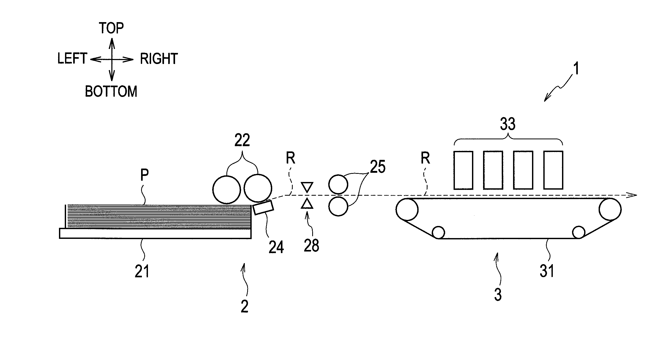
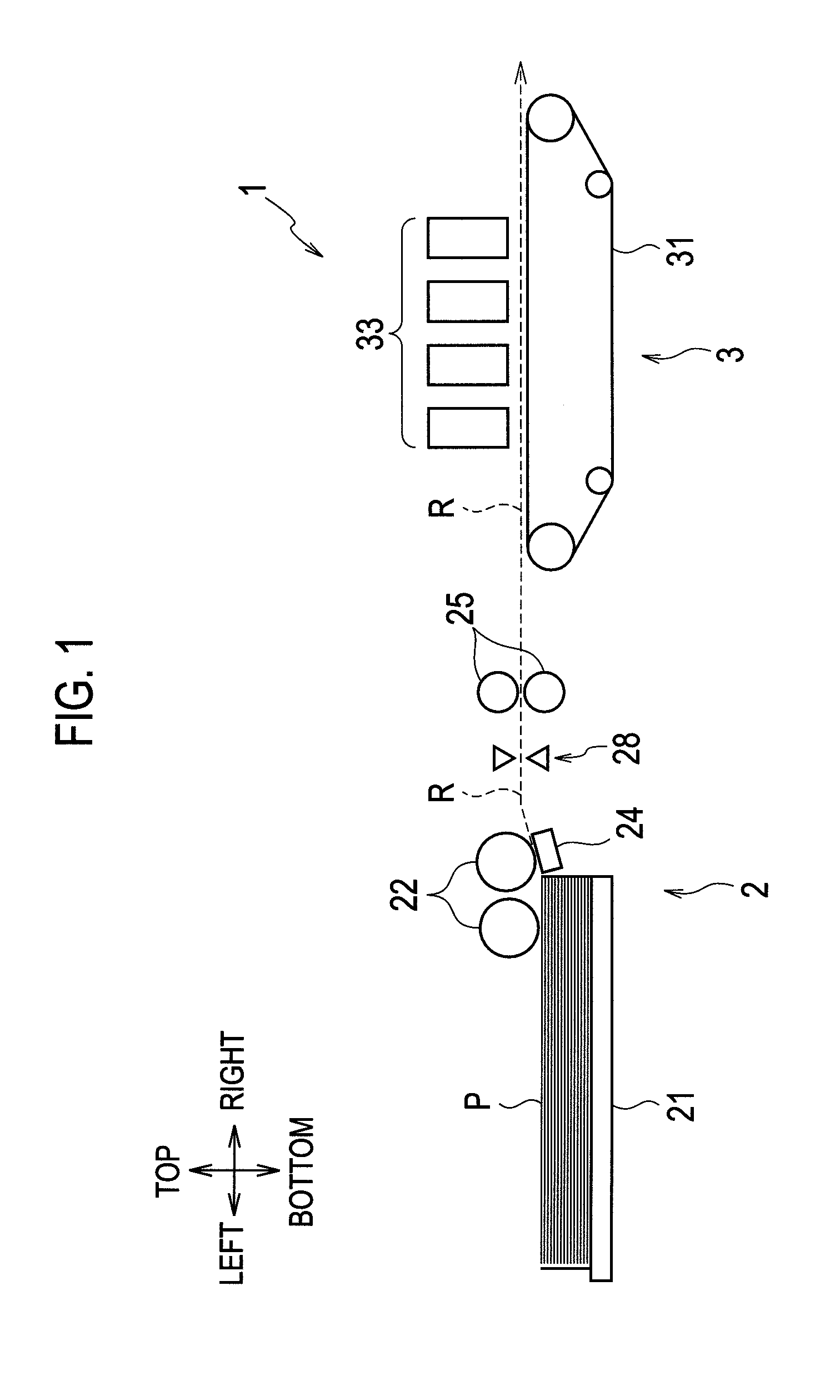
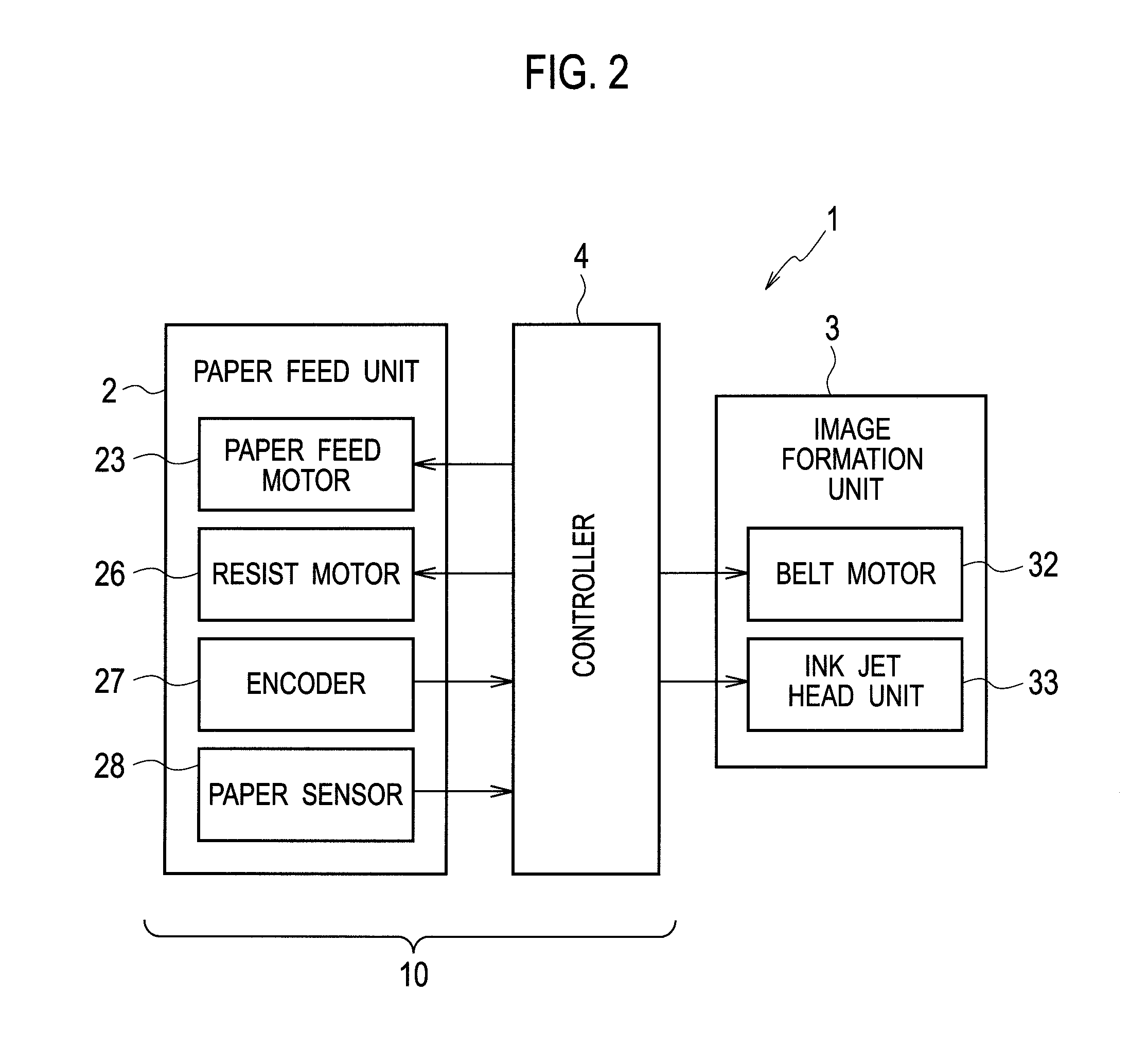
[0031]FIG. 1 is a schematic configuration diagram of an imaging forming apparatus including a paper feeder 10 of the embodiment of the present invention. FIG. 2 is a block diagram showing the configuration of a control system of the image forming apparatus shown in FIG. 1. Top, bottom, left, and right in the following description refer to top, bottom, left, and right shown in FIG. 1, respectively. Moreover, the path shown by the broken line in FIG. 1 is a conveying path R through which sheets are conveyed, and a direction from left to right is the conveying direction. Upstream and downstream in the following description refer to upstream and downstream in the co...


PUM


Abstract

A paper feeder includes a resist roller configured to convey a sheet to an image formation unit, a paper feed roller configured to convey a sheet to the resist roller, and a controller configured to control the paper feed roller such that the paper feed roller first conveys a sheet at a first conveying speed and then conveys the sheet while decelerating from the first conveying speed to a second conveying speed slower than the first conveying speed. The controller sets the first and second conveying speeds in advance to speeds which allow the paper feed roller to convey a single sheet by a predetermined conveying amount in a predetermined driving time period. The controller determines a time point to start a deceleration from the first conveying speed to the second conveying speed to allow a sheet to hit the resist roller at the second conveying speed.

Description

CROSS REFERENCE TO RELATED APPLICATION[0001]This application is based upon and claims the benefit of priority from the prior Japanese Patent Application No. 2011-083728, filed on Apr. 5, 2011, the entire contents of which are incorporated herein by reference.BACKGROUND OF THE INVENTION[0002]1. Field of the Invention[0003]The present invention relates to a paper feeder provided to an image forming apparatus.[0004]2. Description of the Related Art[0005]There are paper feeders which are provided to an image forming apparatus and configured to convey a sheet of paper (hereinafter referred to as sheet) taken out from a paper feed tray to an image formation unit by using resist rollers, the image formation unit including ink jet heads or the like.[0006]In such a paper feeder, while being conveyed by paper feed rollers, a sheet hits the resist rollers and is held against the resist rollers temporarily. In this way, a warpage is formed on the sheet. This corrects oblique conveyance of the s...

Claims


Application Information

Patent Timeline
Patent Type & Authority Applications(United States)
IPC IPC(8): B65H5/06
CPCB65H9/006B65H2513/108B65H2557/242B65H2801/06B65H2513/10B65H9/14B65H5/34B65H2220/02
Inventor YAMAGATA, AKIHIRO
Owner RISO KAGAKU CORP
Why Eureka
Try Eureka