Display and Display Module

a technology of display module and display module, which is applied in the field of display and display module, can solve the problems of disadvantageous increase in the number of components, and achieve the effect of efficient heat radiation without increasing the number of components

Inactive Publication Date: 2012-10-11
FUNAI ELECTRIC CO LTD
View PDF6 Cites 14 Cited by
  • Summary
  • Abstract
  • Description
  • Claims
  • Application Information

AI Technical Summary

Benefits of technology

[0007]The present invention has been proposed in order to solve the aforementioned problem, and an object of the present invention is to provide a display and a display module each capable of efficiently radiating heat generated by a light source without increasing the number of components.

Problems solved by technology

However, the illuminator disclosed in the aforementioned Japanese Patent Laying-Open No. 2007-12416 employs two components, i.e., the light frame and the keep plate, in order to efficiently radiate the heat generated by the LED to both sides of the LED (sides closer to the front and back surfaces of the PCB respectively), and hence the number of components is disadvantageously increased.

Method used


Image

  • Display and Display Module
  • Display and Display Module
  • Display and Display Module

Examples


Embodiment Construction

[0039]An embodiment of the present invention is now described with reference to the drawings.

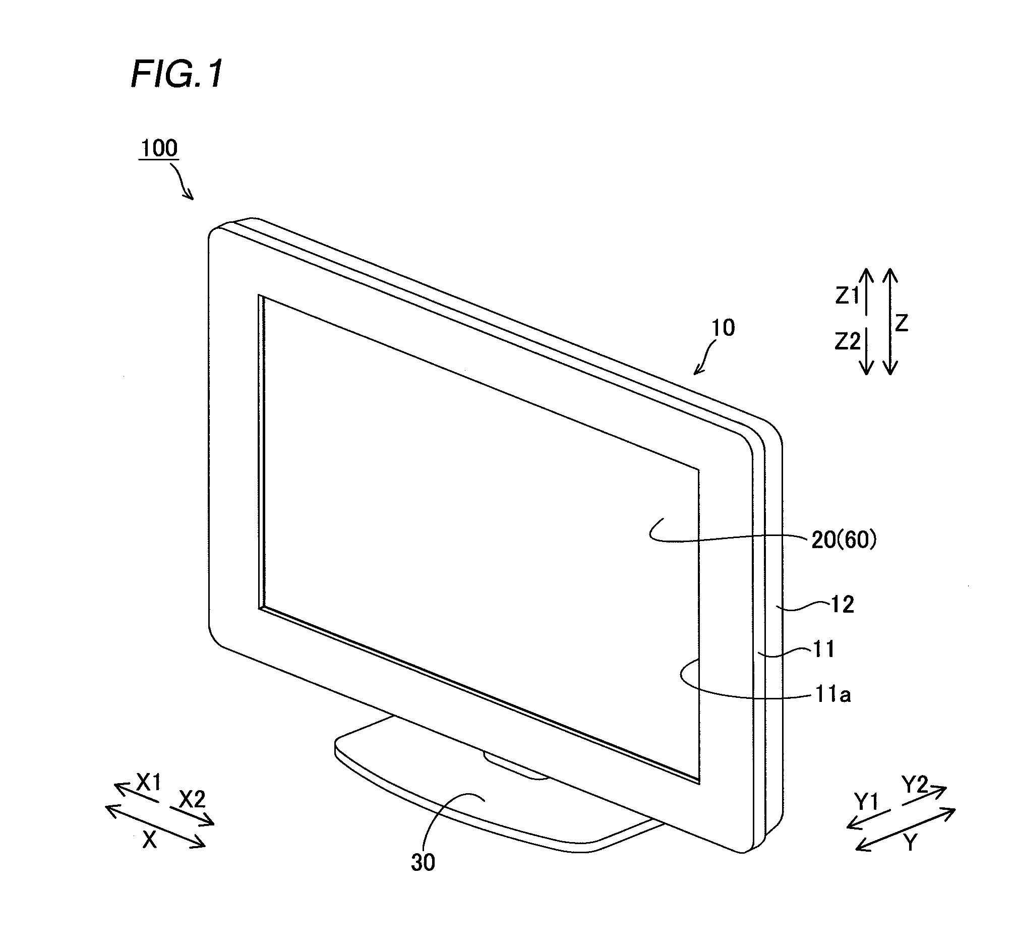
[0040]First, the structure of a liquid crystal television 100 according to the embodiment of the present invention is described with reference to FIGS. 1 to 7. The liquid crystal television 100 is an example of the “display” in the present invention.

[0041]As shown in FIG. 1, the liquid crystal television 100 according to the embodiment of the present invention includes a television body 10 having a display portion 20 displaying images and a stand member 30 supporting the television body 10 from below (along arrow Z2).

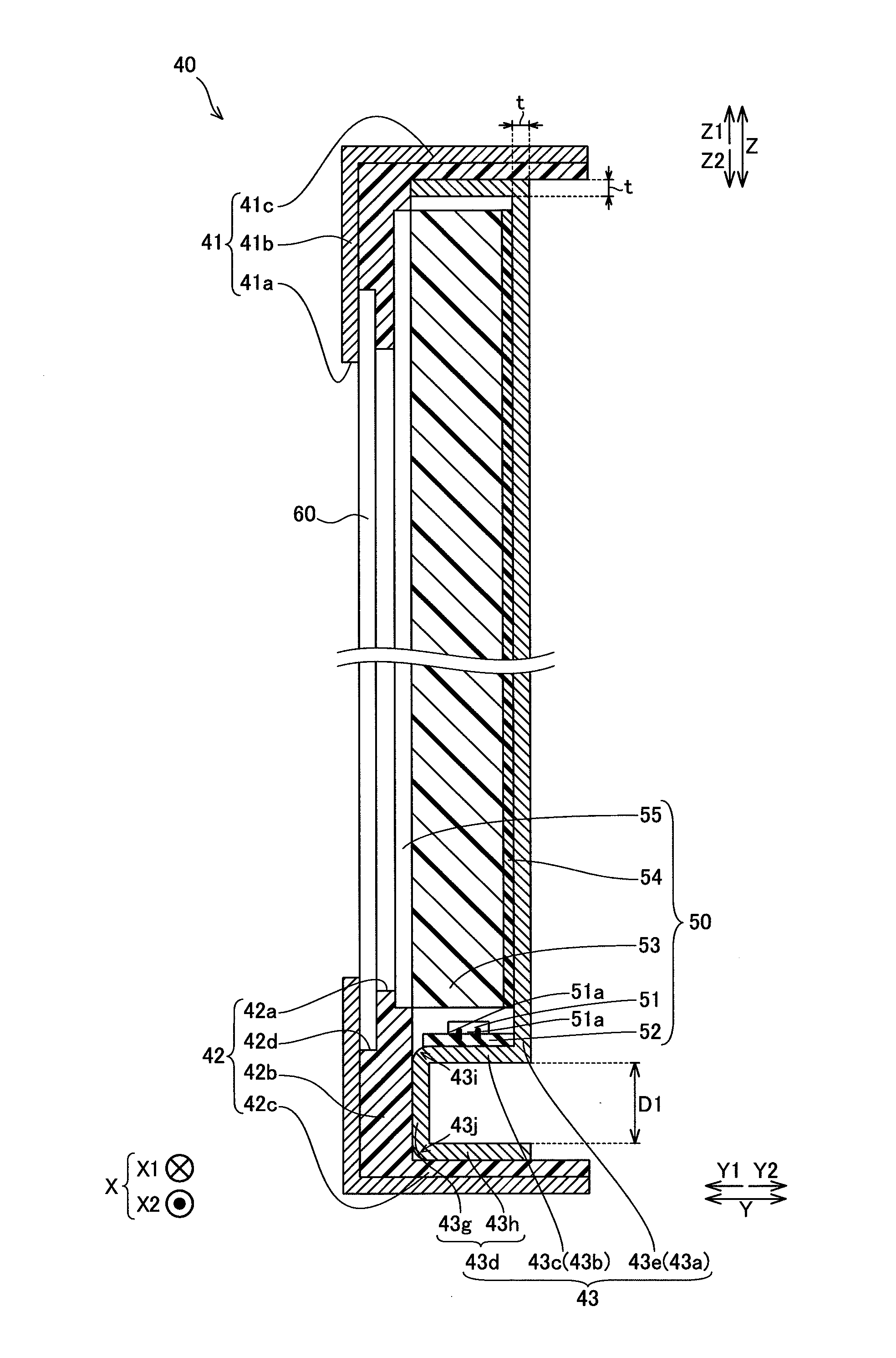
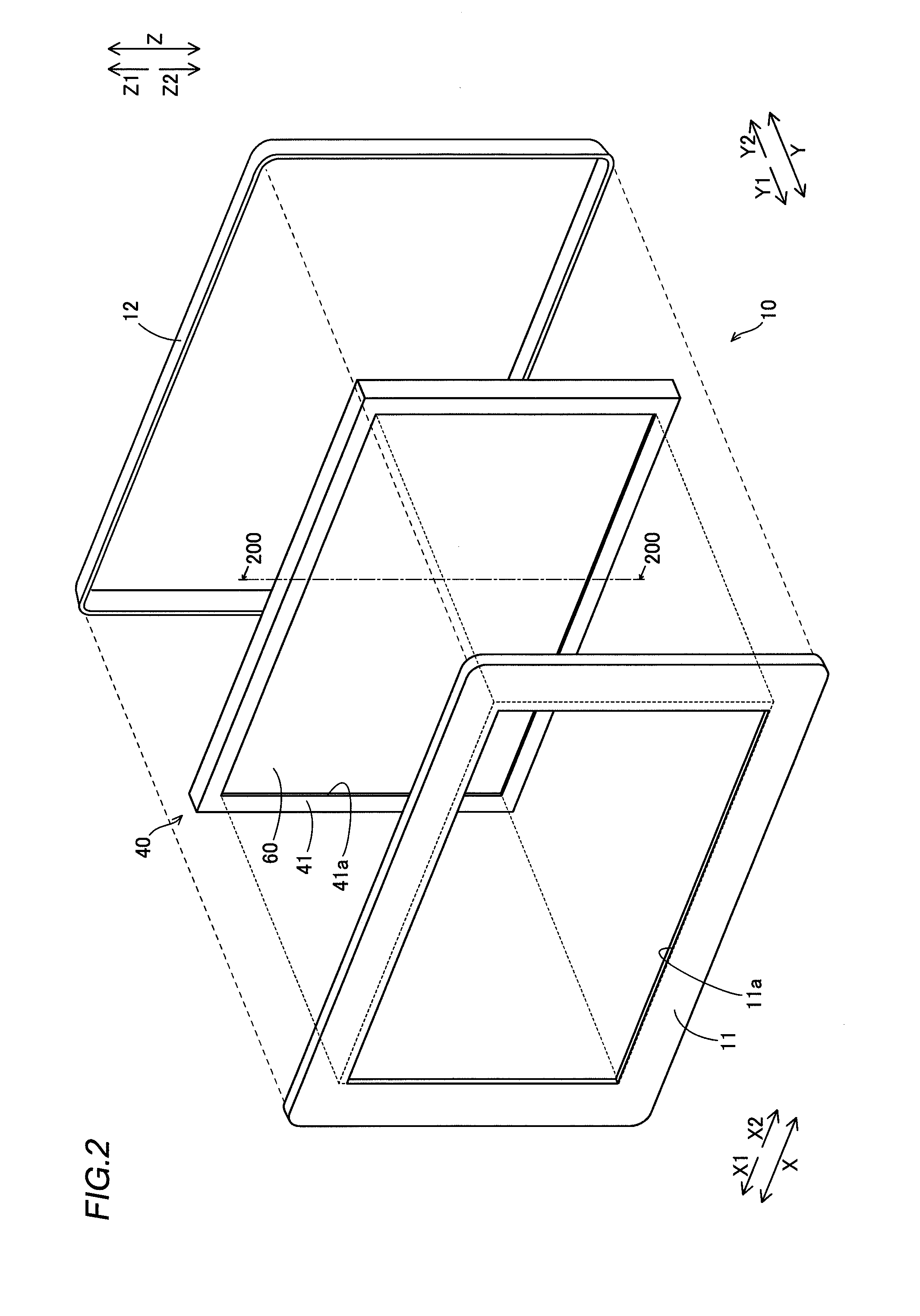
[0042]As shown in FIGS. 1 and 2, the television body 10 includes front and rear cabinets 11 and 12 made of resin and a liquid crystal display module 40 having a liquid crystal display cell 60 constituting the display portion 20. The front and rear cabinets 11 and 12 are examples of the “housing” in the present invention. The liquid crystal display module 40 and the liquid crysta...


PUM

PropertyMeasurementUnit
thicknessaaaaaaaaaa
lengthaaaaaaaaaa
thicknessaaaaaaaaaa

Abstract

This display includes a display module including a substrate mounted with a light source, a light guide guiding light received from the light source and a platelike member of a metal radiating heat generated by the light source. The platelike member integrally includes a substrate mounting portion, a first heat radiation portion extending from a first end portion of the substrate mounting portion oppositely to the light guide and a second heat radiation portion extending from a second end portion of the substrate mounting portion oppositely to the first heat radiation portion.

Description

BACKGROUND OF THE INVENTION[0001]1. Field of the Invention[0002]The present invention relates to a display and a display module, and more particularly, it relates to a display and a display module each including a substrate mounted with a light source and a platelike member of a metal having a function of radiating heat generated by the light source.[0003]2. Description of the Background Art[0004]A display including a substrate mounted with a light source and a platelike member of a metal having a function of radiating heat generated by the light source is known in general, as disclosed in Japanese Patent Laying-Open No. 2007-12416, for example.[0005]The aforementioned Japanese Patent Laying-Open No. 2007-12416 discloses an illuminator including a PCB (Printed Circuit Board) (substrate) mounted with an LED (Light-Emitting Diode) (light source), a light frame consisting of a sheet metal member having thermal conductivity and a keep plate. This illuminator is employed as a backlight f...

Claims


Application Information

Patent Timeline
Patent Type & Authority Applications(United States)
IPC IPC(8): G02F1/13357F21V8/00
CPCG02B6/0073G02B6/0085G02F1/133308G02F1/133615G02B6/0068G02F2001/133317G02F2001/13332G02F2001/133628G02F2001/133314G02F1/133314G02F1/133317G02F1/13332G02F1/133628
Inventor HORIUCHI, HIROFUMI
Owner FUNAI ELECTRIC CO LTD
Why Eureka
Try Eureka