Lawnmower safety

a safety and lawnmower technology, applied in the field of walk-behind lawnmowers, can solve the problem of not providing movement power for the mower

Active Publication Date: 2012-10-18
MASPORT
View PDF5 Cites 5 Cited by
  • Summary
  • Abstract
  • Description
  • Claims
  • Application Information

AI Technical Summary

Benefits of technology

[0018]U.S. Pat. No. 4,172,351 describes a mower which has a detachable side shield. The purpose of the side shield is to prevent the ejection of items that might cause harm or damage from the interior cuttin...

Problems solved by technology

For ‘push’ type or user-propelled mowers of either the electric or motor mower type, a user is required to push the mower in order to move it ...

Method used


Image

  • Lawnmower safety
  • Lawnmower safety
  • Lawnmower safety

Examples


Embodiment Construction

[0099]The present invention provides improvements to a lawnmower which also includes a chipper or shredder.

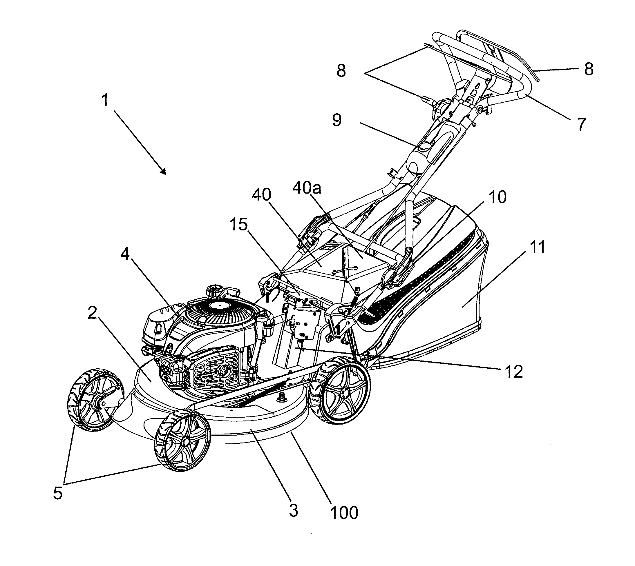
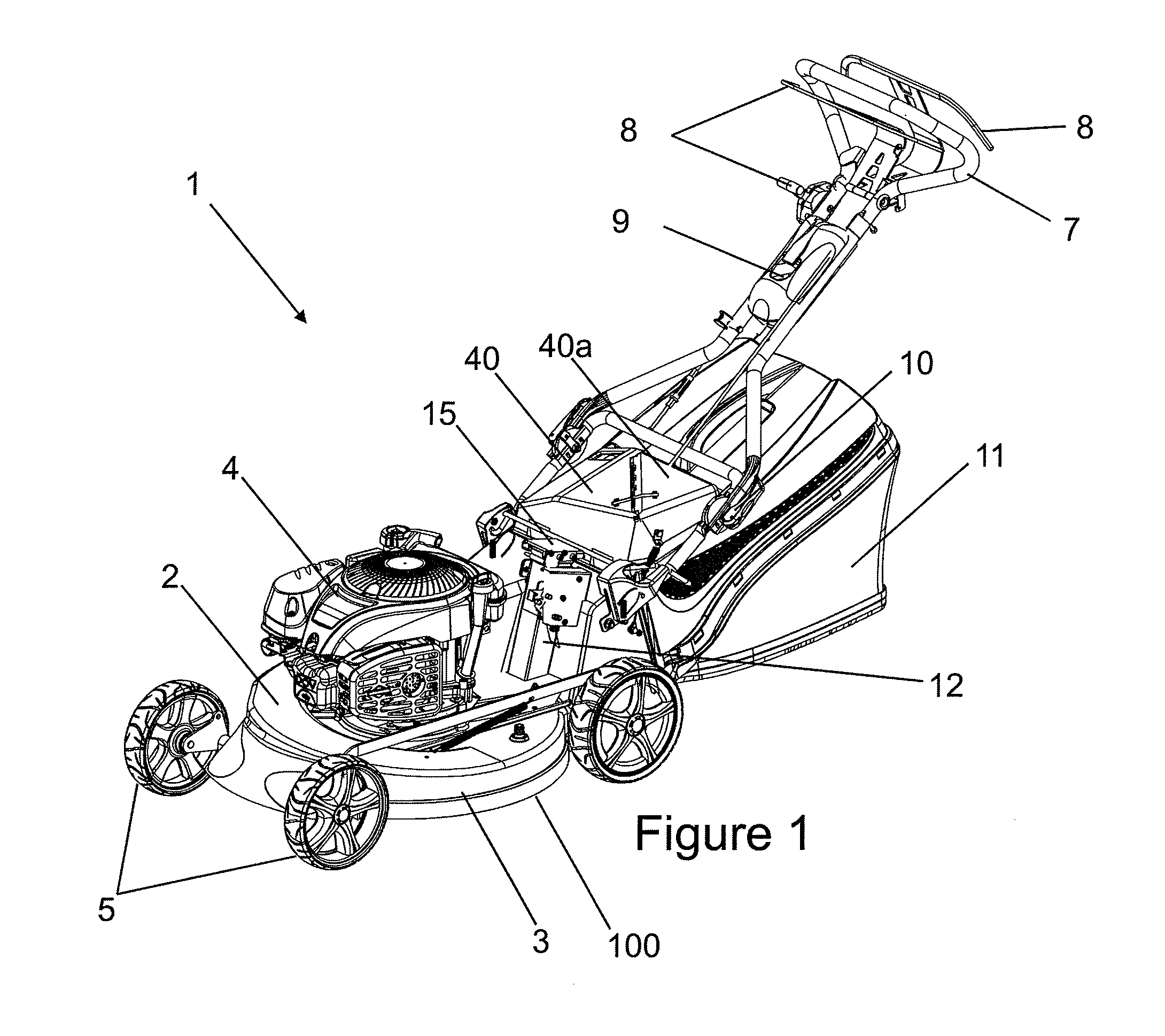
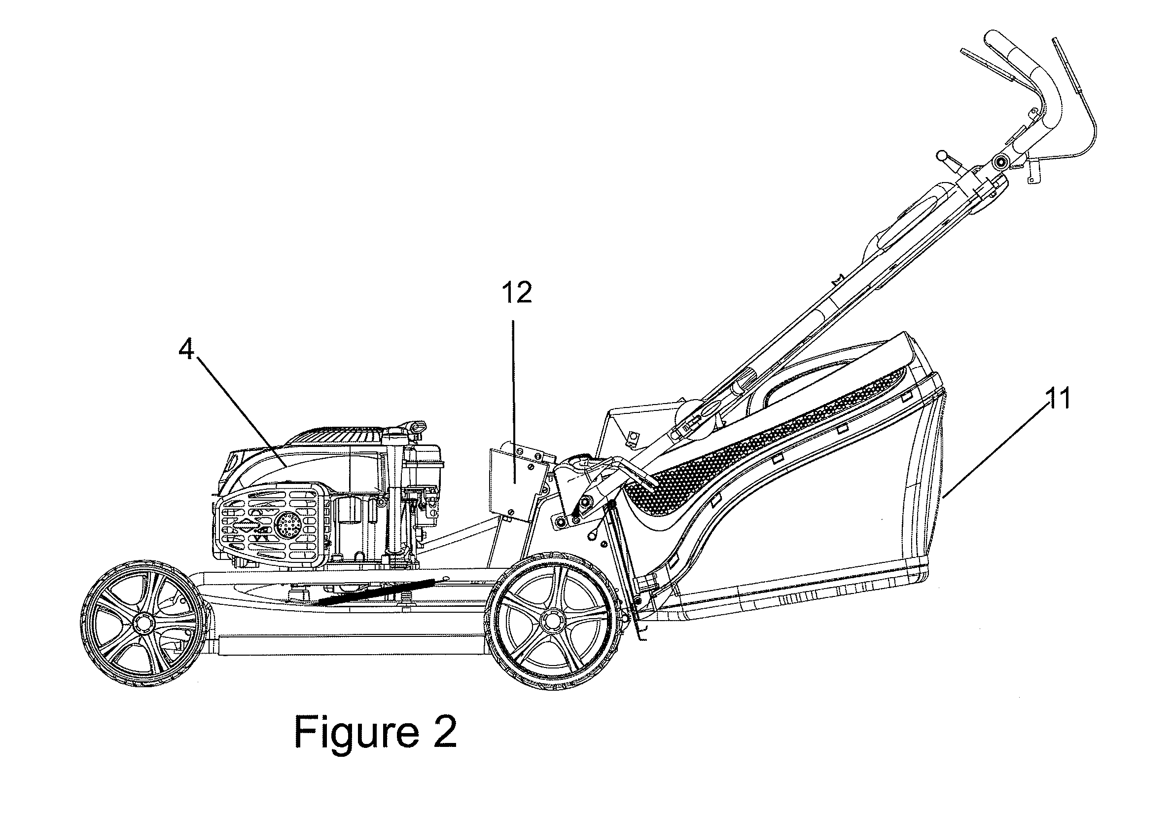
[0100]A mower 1 according to one preferred form of the invention is shown in FIGS. 1, 2 and 3. The main part of the mower is a deck 2 which is generally shaped to have the overall form of a volute, the deck including an expanding funnel 60 which forms part of the volute and which runs along the right hand side of the deck, expanding towards the rear of the mower. The rear of the mower deck 2 at least partly forms an exit or exit aperture for the funnel 60. The mower also has an integral side wall 3 which is arranged around or runs around at least part of the outer perimeter of the deck 2. The deck 2 and the side wall 3 enclosing a cutting area or cutting space 70 in use, under the deck 2 and inside the perimeter of the side wall 3. A motor 4 is attached to the mower 1, on the outside top of the deck 2, approximately at the centre of the deck 2. In the preferred form, the motor ...


PUM


Abstract

The invention relates to safety improvements for mowers incorporating a chipper, and/or catcher. In one aspect the invention provides safety improvements that only allow operation of the chipper when the mower is below a predetermined threshold ride height. In another aspect, the mower includes one or more side skirts to prevent body parts from entering the cutting zone under the mower. In a still further aspect, the mower has a rear flap including a sub-flap. The mower is arranged so that the sub flap remains closed when a catcher is installed.

Description

BACKGROUND TO THE INVENTION[0001]1. Field of the Invention[0002]The present invention relates to walk-behind lawnmowers for cutting grass. In particular the invention relates to safety improvements for mowers incorporating a shredder or chipper, and / or catcher.[0003]2. Summary of the Prior Art[0004]Push-behind or walk-behind lawnmowers with a powered cutting mechanism are well-known. Mowers of this type normally include a generally centrally located deck or housing that has an integral side wall which runs around the perimeter of a generally horizontally oriented deck or housing, and which is aligned substantially vertically running downwards towards the ground. The mower also has a powered cutting mechanism such as a pair of rotating blades, or a plurality of blades, located under the deck and inside the integral side wall. Items such as the engine or power source for the blades are generally located above the deck, attached to the top of the deck. The area bounded by the deck and ...

Claims


Application Information

Patent Timeline
IPC IPC(8): A01D43/06A01D34/82
CPCA01D34/828A01D75/20A01D42/00A01D43/063
Inventor HARAQIA, AGRONMCKAY, DAVIDBOSWELL, GORDON
Owner MASPORT
Why Eureka
Try Eureka