Receiver for an autoloading firearm

a receiver and autoloading technology, applied in the field of firearms, can solve the problems of easy damage to the feed lips of the magazine, the design's operable principles have not been significantly improved, and the well of the factory magazine is narrow and easy to miss, so as to increase the margin of error for the user, the effect of dragging on the operating system

Active Publication Date: 2012-10-18
LWRC INTERNATIONAL
View PDF0 Cites 74 Cited by
  • Summary
  • Abstract
  • Description
  • Claims
  • Application Information

AI Technical Summary

Benefits of technology

[0022](e) To provide a forward assist option which does not require the user to remove his hand from the firing grip of the firearm.
[0023]Still further objects and advantages will become apparent from a consideration of the ensuing description and drawings.
[0024]The present firearm design is an improvement of the prior art receiver system typified by the “M-16” design concept and is suitable, for both direct and indirect gas operating systems. An angled flare is added to the bottom of the magazine well as a means to assist the users of the host firearm in the rapid insertion of a magazine. This magazine flare will provide a larger opening at the base of the magazine well, thus allowing an increased margin of error for the user when attempting to quickly, often under stress, insert the loaded magazine. With the addition of a raised shelf in the lower receiver of the host firearm, the rear or “boss” of the bolt carrier is prevented from tilting down, from the upper receiver, into the lower receiver. This tilt creates drag on the operating system and can damage the receiver extension. The charging handle being moved to the side of the receiver offers several marked improvements over the prior art. Positioning the charging handle on the left side allows the shooters primary firing hand to stay on the pistol grip while the weapon is being loaded or unloaded. Further, it is possible for the shooter to maintain the sight alignment and sight picture of his firearm because the head no longer needs to be removed as is the case when the prior art charging handle is retracted to the rear of the receiver. By eliminating the void for the charging handle, hot gas and carbon are no longer able to exit from the rear of the upper receiver into the shooter's face. Succinctly stated, the improved receiver design for an M-16 type rifle presented by the herein described invention can be distinguished from the prior art by a charging handle protruding from the left side of the receiver, a semi-circular shelf being located in the lower receiver in front of the receiver extension, and a magazine well flare which is integrally machined into the lower receiver.

Problems solved by technology

This rifle design itself has undergone many refinements to improve its functional reliability, to expand its mission roles, and to reduce its manufacturing costs, yet the design's operable principles have not been significantly improved.
The factory magazine well is narrow and easy to miss when the users are under pressure.
Further, damage to the feed lips of the magazine can occur when the user drives the magazine into the side of the magazine well.
Unfortunately these designs are reliant on tension, bolts or other methods to remain affixed.
This tilting creates drag in the system which hinders the proper operation of the firearm and leads to premature wear of the lower, receiver and leads to numerous cycling related issues.
This solution does not entirely solve the problem in M16 type firearms, especially those which utilize higher pressure cartridges such as .308win.
Having gas blow back from the firearm operating system being vented into the user's face is not only distracting but also presents a potential health problem for the shooter.
Charging handles such as the one designed by PRJ (U.S. Pat. No. 6,311,603) reduce the gas blow back, but do not eliminate it.
Similar side charging handles are used on the FN F AL type rifle, and its variation, but the prior art does not teach how to make an operable combination of components.
This magazine flare will provide a larger opening at the base of the magazine well, thus allowing an increased margin of error for the user when attempting to quickly, often under stress, insert the loaded magazine.
This tilt creates drag on the operating system and can damage the receiver extension.

Method used


Image

  • Receiver for an autoloading firearm
  • Receiver for an autoloading firearm
  • Receiver for an autoloading firearm

Examples


Embodiment Construction

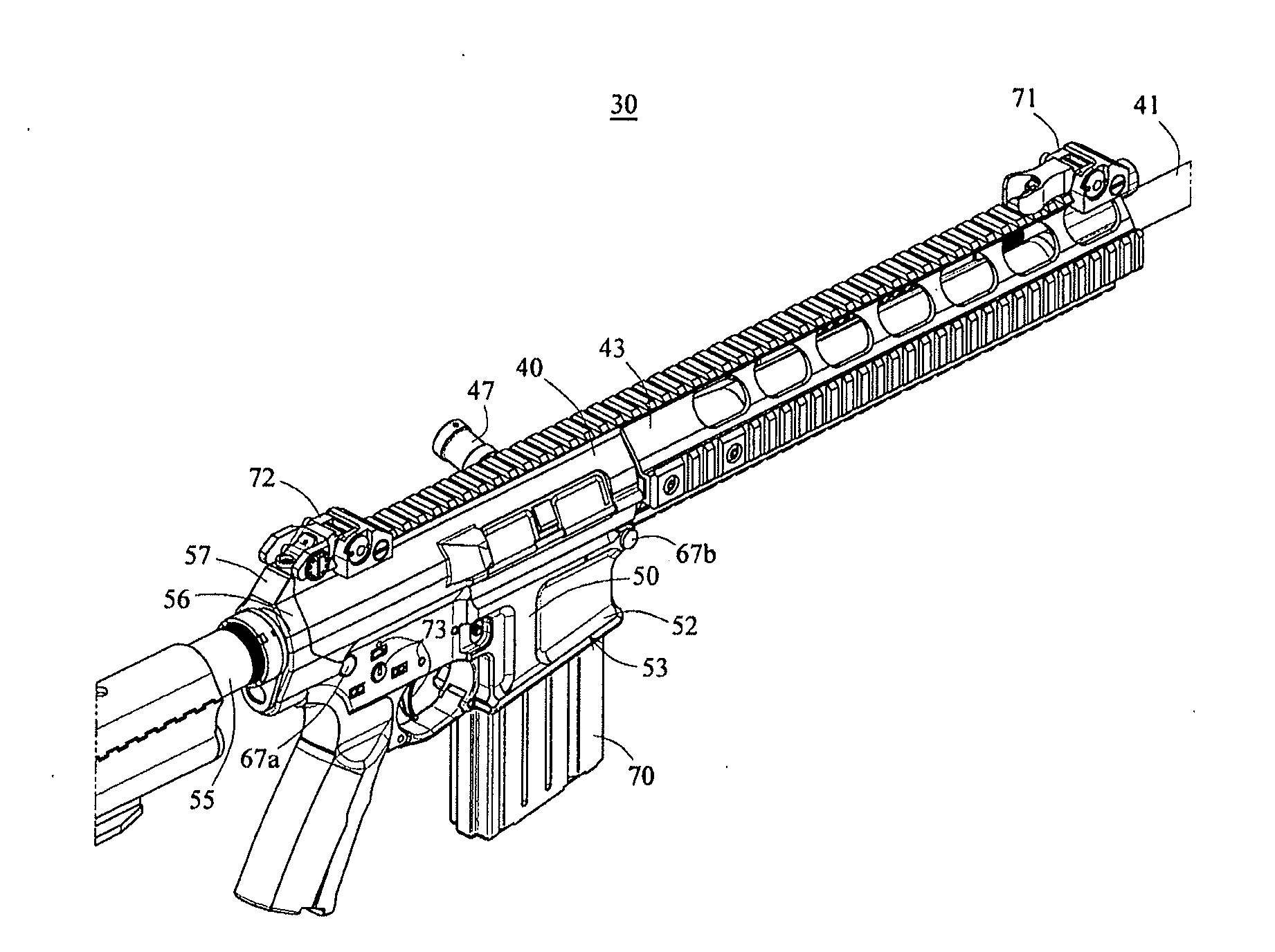
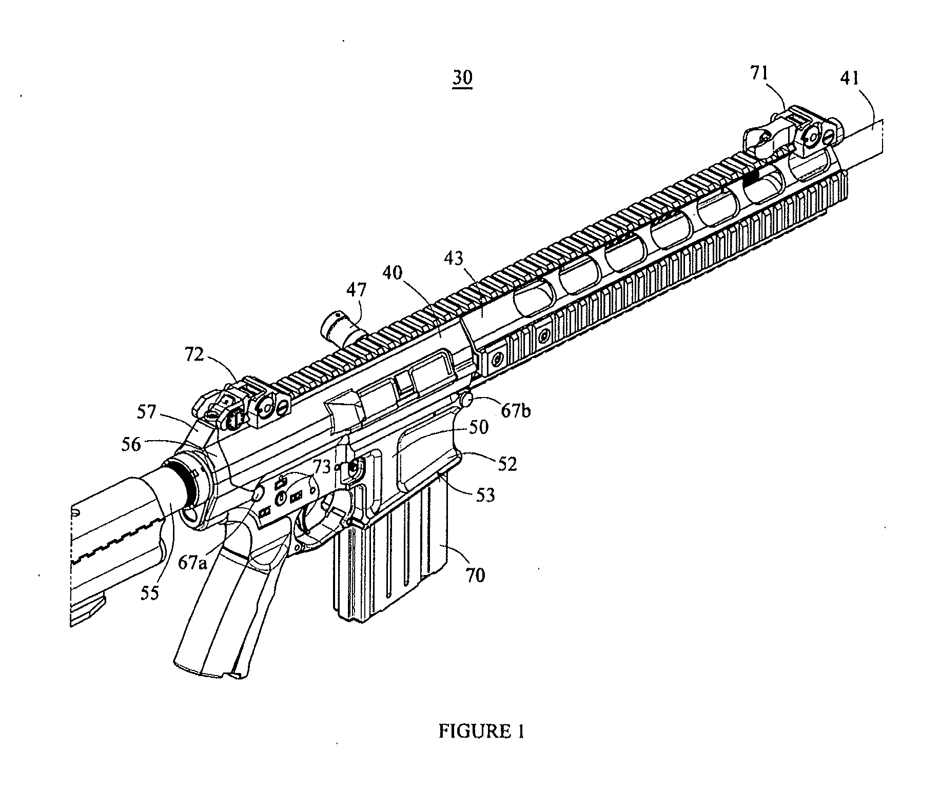
[0033]Turning now to the drawings in which like reference characters indicate corresponding elements throughout the several views, as used herein, the word “front”, or “distal” corresponds to the firing direction the assembled firearm 30 is facing in FIG. 1 (i.e., to the right as shown in FIG. 1); “rear” or “proximal” or “back” corresponds to the direction opposite the firing direction of the assembled firearm 30 (i.e., to the left as shown in FIG. 1).

[0034]Unless otherwise specified, the various components which make up the trigger mechanism, buttstock assembly, bolt carrier assembly, barrel assembly are as those found on the prior art M16 / M4 rifles and their various embodiments.

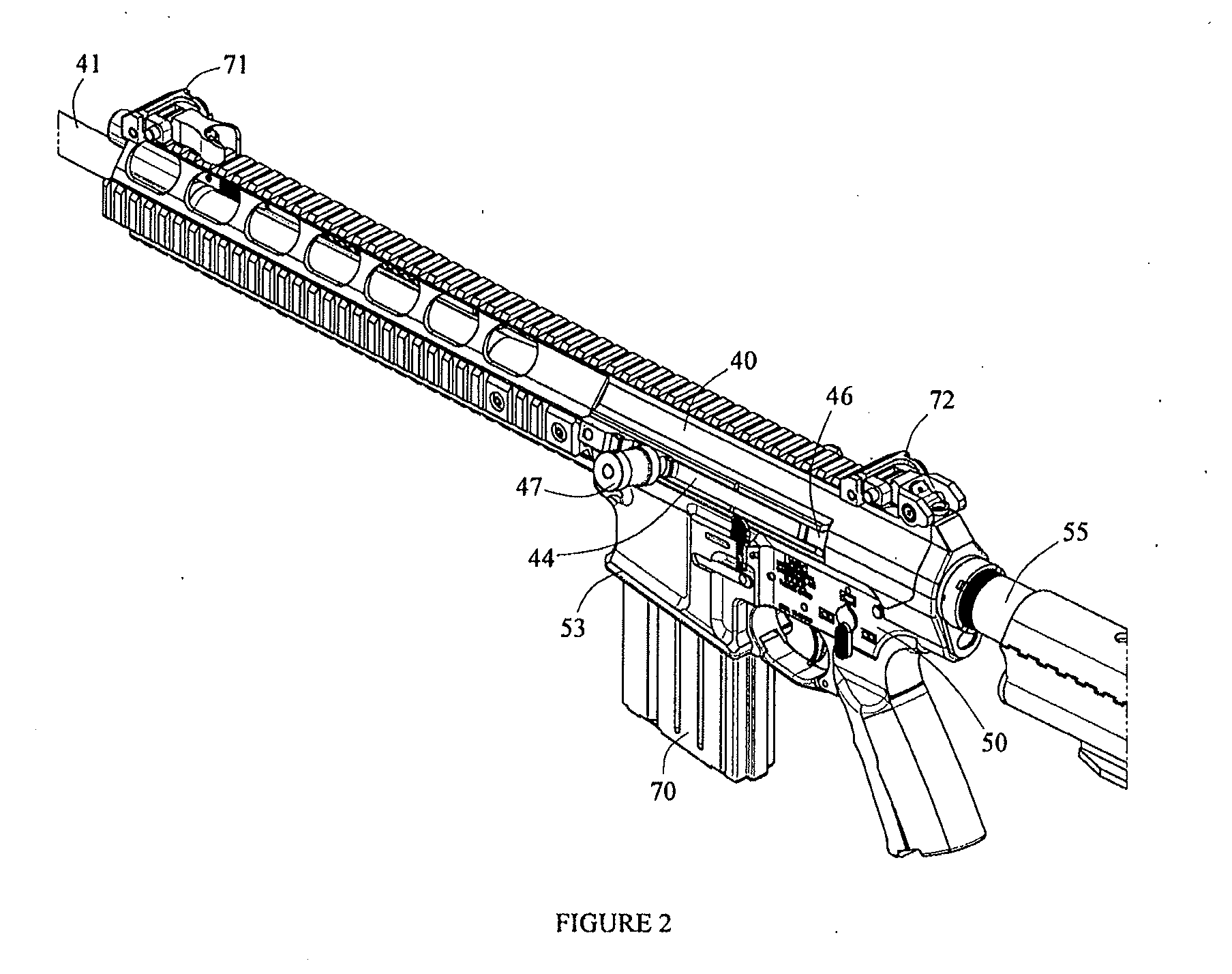
[0035]Referring to FIGS. 1 & 2, there is shown a side elevation view of an autoloading firearm 30 capable of full automatic or semiautomatic fire and incorporating features in accordance with the preferred embodiment of the present invention. Although the present invention will be described with reference ...


PUM


Abstract

Improved receiver set for an indirect or direct gas operated firearm wherein the charging handle has been moved to the side of the upper receiver, the magazine well has been flared open to better receive a magazine, and the lower receiver has a semi-circular shelf in the rear which supports the proximal end of the bolt carrier as it is longitudinally displaced due to firing of the weapon.

Description

[0001]This is a continuation application of co-pending U.S. application Ser. No. 12 / 381,240, filed Mar. 10, 2009, the priority of which is hereby claimed.BACKGROUND OF THE INVENTION[0002]1. Field of the Invention[0003]The disclosures herein relate generally to firearms. Specifically, the herein disclosure relates to the M16 series of firearms, and its derivatives. The improved receiver system described herein provides a side charging handle, a flared magazine well for more readily receiving a magazine, and a support feature in the lower receiver which prevents carrier tilt.[0004]2. Description of the Prior Art[0005]All U.S. patents and applications and all other published documents mentioned anywhere in this application are incorporated herein by reference in their entirety.[0006]Without limiting the scope of the invention, a brief summary of some of the claimed embodiments of the invention is set forth below. Additional details of the summarized embodiments of the invention and / or ...

Claims


Application Information

Patent Timeline
Patent Type & Authority Applications(United States)
IPC IPC(8): F41A5/18
CPCF41A5/18F41A3/66
Inventor GOMEZ, JESUS S.
Owner LWRC INTERNATIONAL
Why Eureka
Try Eureka