Torque sensor and power steering system

a technology of torque sensor and power steering system, which is applied in the direction of instruments, force/torque/work measurement apparatus, transportation and packaging, etc., can solve the problem that the above-mentioned document system is still insufficient in setting

Inactive Publication Date: 2012-10-18
HITACHI AUTOMOTIVE SYST STEERING
View PDF10 Cites 16 Cited by
  • Summary
  • Abstract
  • Description
  • Claims
  • Application Information

AI Technical Summary

Problems solved by technology

However, the system of the above-mentioned document is still insufficient in setting of characteristics of the resolvers for the use in a torque sensor.

Method used


Image

  • Torque sensor and power steering system
  • Torque sensor and power steering system
  • Torque sensor and power steering system

Examples


Embodiment Construction

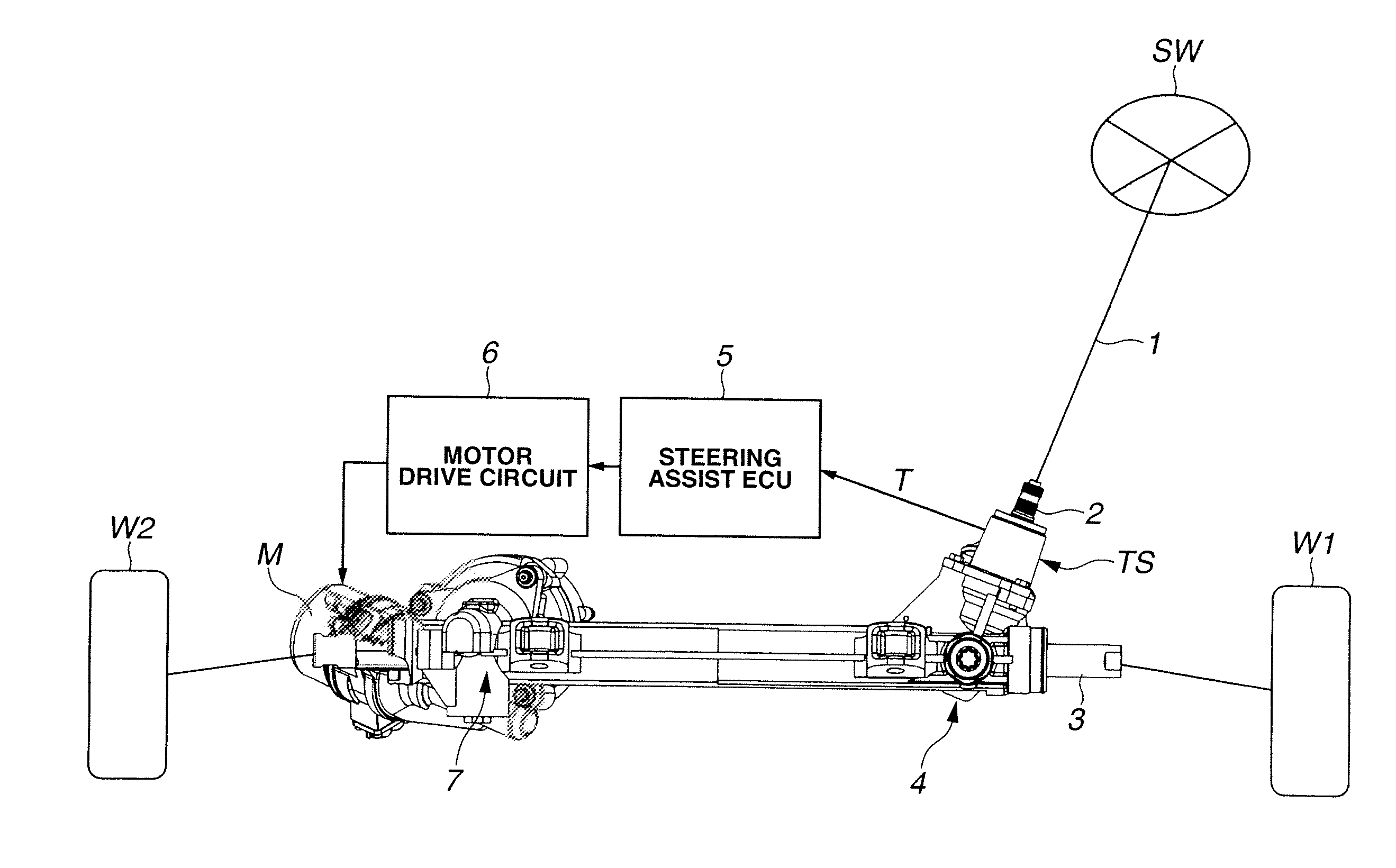
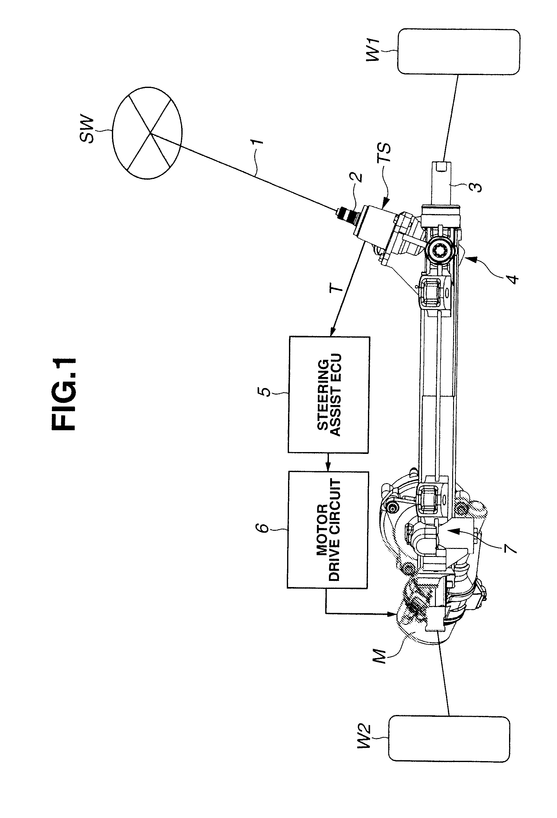
[0016]FIG. 1 shows an apparatus according to one embodiment of the present invention. In this embodiment, the apparatus is a power steering system or apparatus. The power steering system of the example shown in FIG. 1 includes a pinion shaft 2 receiving rotation from a steering wheel SW through a steering shaft 1, and a rack shaft 3 arranged to move linearly in response to rotation of pinion shaft 2 and to steer left and right steerable wheels W1 and W2 connected with the left and right ends of rack shaft 3, respectively. The pinion shaft 2 and rack shaft 3 form a first steering mechanism 4, which, in this example, is a first rack and pinion mechanism 4, for manual steering operation.

[0017]The rack shaft 3 is connected with a motor M controlled by a steering assist ECU 5 and a motor drive circuit 6 serving as a motor drive section, through a second steering mechanism 7, which, in this example, is a second rack and pinion mechanism 7, for steering assist. Steering assist ECU 5 receiv...


PUM


Abstract

First and second shafts are connected with each other through a torsion bar and arranged to rotate relative to each other within a relative rotational angle range A. A s torque sensor includes first and second resolvers for sensing the angular potions of the first and second shafts, respectively. The first resolver produces a periodical first resolver output signal so that the number X1 of cycles per revolution of the first shaft is smaller than 360 / A (X1<360 / A). The second resolver produces a periodical second resolver output signal so that the number X2 of cycles per revolution of the second shaft is smaller than 360 / A (X2<360 / A).

Description

BACKGROUND OF THE INVENTION[0001]The present invention relates to a torque sensor and a power steering apparatus or system.[0002]A Japanese patent document, JP 2010-286310A discloses a vehicular power steering system including a torque sensor for sensing a steering torque caused by a driver's steering operation of turning a steering wheel, and a controller to impart a steering assist force to the steering system or steering linkage in accordance with the sensed steering torque. The torque sensor includes a torsion bar connecting first and second shafts, and first and second resolvers provided, respectively, on the first and second shafts and arranged to sense the relative rotation between the first and second shafts and to calculate the torque transmitted through the torsion bar, from the quantity of the relative rotation between the first and second shafts or the quantity of torsion of the torsion bar.SUMMARY OF THE INVENTION[0003]However, the system of the above-mentioned document...

Claims


Application Information

Patent Timeline
Patent Type & Authority Applications(United States)
IPC IPC(8): B62D6/10B62D5/04G06F19/00
CPCG01L5/221B62D6/10
Inventor SHIINO, KOHTARO
Owner HITACHI AUTOMOTIVE SYST STEERING
Why Eureka
Try Eureka