Electro-hydraulic fan drive cooling and steering system for vehicle

a technology of electrohydraulic system and cooling fan, which is applied in the direction of positive displacement liquid engine, fluid coupling, servomotor, etc., can solve the problems of variable displacement pump, high engine horsepower, and relatively high fuel consumption,

Inactive Publication Date: 2007-01-02
HYDRA FAB FLUID POWER
View PDF18 Cites 48 Cited by
  • Summary
  • Abstract
  • Description
  • Claims
  • Application Information

AI Technical Summary

Problems solved by technology

However, these systems consume a high engine horsepower to drive the hydraulic system making the fuel consumption relatively high.
One disadvantage of this known hydraulic drive assembly is that it does use a variable displacement pump which generally speaking is more expensive than and heavier than a fixed displacement pump.

Method used


Image

  • Electro-hydraulic fan drive cooling and steering system for vehicle
  • Electro-hydraulic fan drive cooling and steering system for vehicle
  • Electro-hydraulic fan drive cooling and steering system for vehicle

Examples


Embodiment Construction

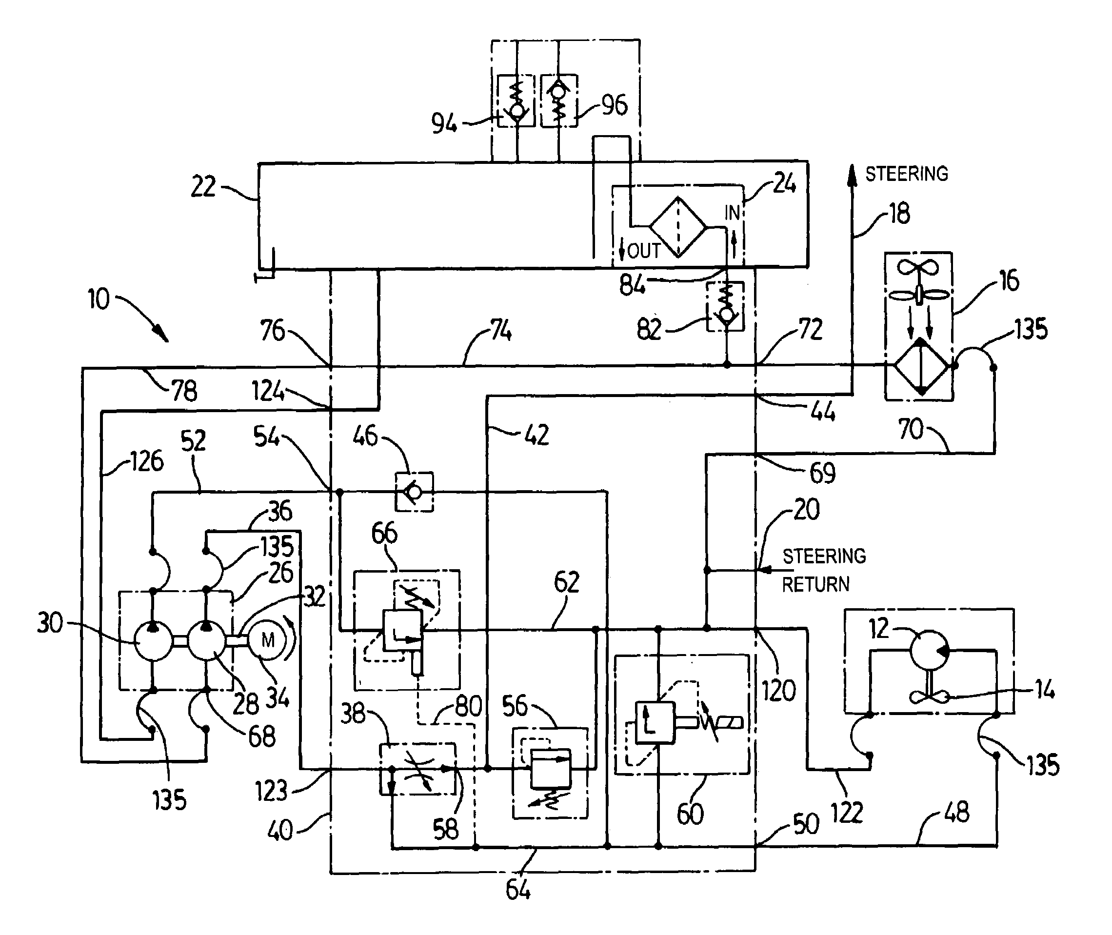
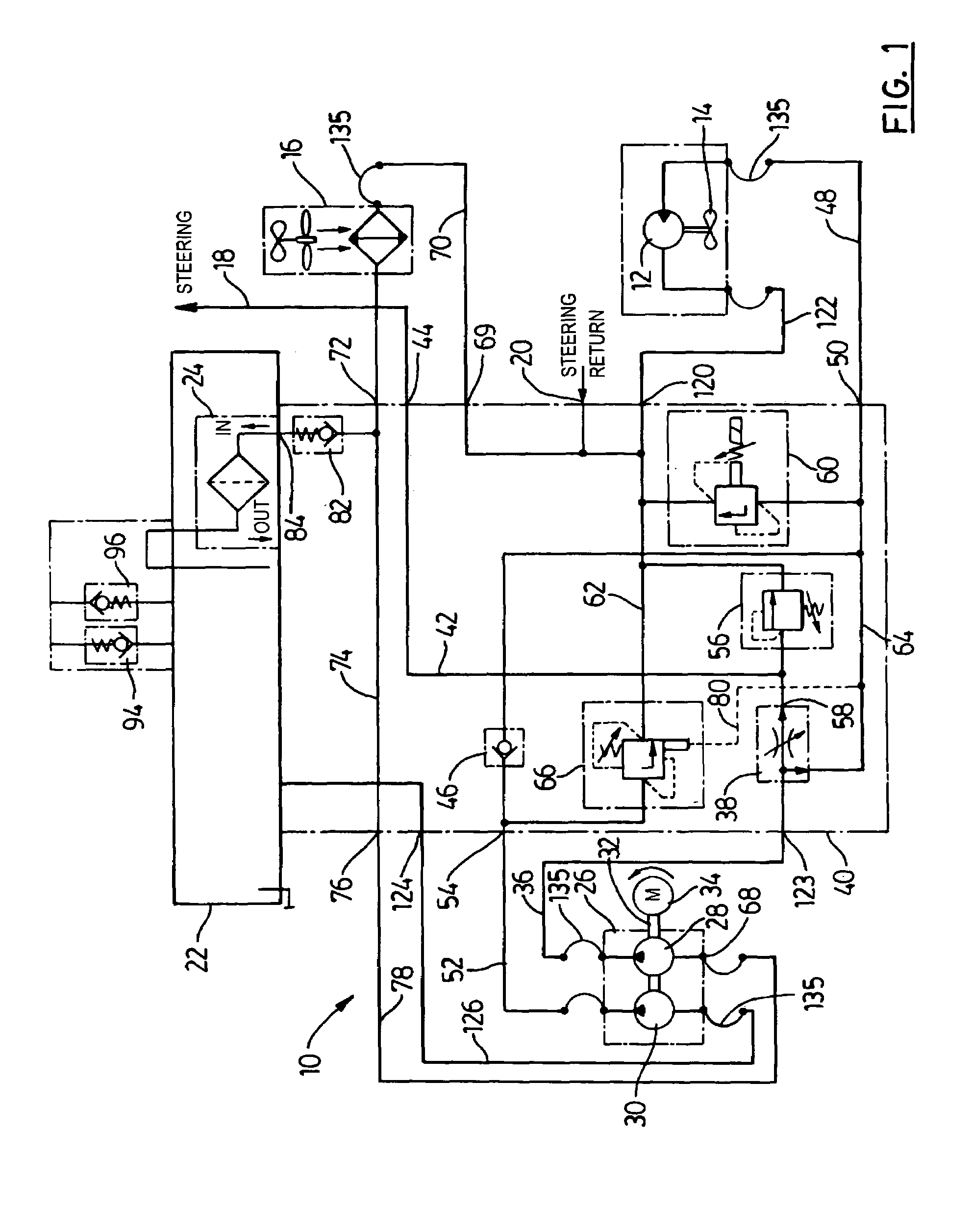
[0024]FIG. 1 illustrates schematically a hydraulic circuit 10 that can be used to provide a preferred version of an electro-hydraulic system according to the invention. Included in FIG. 1 are known vehicle components that can be attached to this hydraulic circuit, for example, standard components found on a vehicle such as a bus or truck. These components include a hydraulic fan motor 12, a standard cooling fan 14 connected thereto, and a cooler unit 16. Although not shown in FIG. 1, it will also be understood that the hydraulic circuit 10 in use is connected to a power steering unit, the inlet of which can be connected to hydraulic line 18. The outlet of the power steering unit is connected to the hydraulic circuit 10 at connection point 20.

[0025]Before discussing the major components of the hydraulic circuit in detail, there will now be provided a general outline of this hydraulic circuit and an explanation of how the major components interact with one another. Shown at the top of...


PUM


Abstract

An electro-hydraulic system for operating a cooling fan and providing hydraulic fluid to a power steering system of the vehicle includes a hydraulic pump unit including first and second fixed displacement pumps and a common drive shaft for these pumps. A hydraulic fluid reservoir is connected to the inlet of each of the pumps. A priority valve is operatively connected to the outlet of the first pump and has an outlet connectible to the power steering system. This valve also has a second outlet connectible to a hydraulic motor for the cooling fan. This valve is arranged to provide a constant flow of hydraulic fluid to the power steering system. A hydraulic line connects an outlet of the second pump to the hydraulic motor. Hydraulic fluid flow through this line is combined with hydraulic fluid flow from the first pump to drive the motor. An electro-hydraulic proportional control valve has an inlet connected to the aforementioned line and an outlet connectible to the reservoir inlet and this control valve controls and limits the rotational speed of the motor. An electronic control device electrically operates and controls the control valve during use of the system.

Description

PRIOR APPLICATION[0001]This application is based in part on and claims priority on the basis of earlier filed U.S. Provisional Patent Application Ser. No. 60 / 555,319 filed Mar. 23, 2004.BACKGROUND OF THE INVENTION[0002]This invention relates to hydraulic and electro-hydraulic systems for vehicles and, in particular, to an electro-hydraulic system for driving a cooling fan motor and operating a power steering system.[0003]A variety of drive systems are known in the vehicle manufacturing industry for driving a cooling fan used to cool a vehicle engine. For example, hydro-mechanical systems have been developed and provided for large vehicles such as buses. However, these systems consume a high engine horsepower to drive the hydraulic system making the fuel consumption relatively high.[0004]Electro-hydraulic systems to operate a cooling fan in a vehicle and to operate other vehicle systems have also been proposed in the past. An advantage of such a system to operate a cooling fan for a ...

Claims


Application Information

Patent Timeline
Patent Type & Authority Patents(United States)
IPC IPC(8): F16D31/02B62D5/07F01P5/04F01P7/04F04B49/06F15B11/17
CPCF16D31/02
Inventor DESJARDINS, YVON CLARENCECOTE, SYLVAIN RAYMONDDOUTRE, PHILLIPPE LOUISYETTER, JAMES EDWARD
Owner HYDRA FAB FLUID POWER
Why Eureka
Try Eureka