Inspection system

a technology of inspection system and support, applied in the direction of material analysis using wave/particle radiation, instruments, nuclear engineering, etc., can solve the problems of correspondingly high weight of the support to be moved, and achieve the effects of reducing the amount of leakage radiation into the environment, simple mechanical design, and stable alignmen

Inactive Publication Date: 2012-10-18
SIEMENS AG
View PDF3 Cites 6 Cited by
  • Summary
  • Abstract
  • Description
  • Claims
  • Application Information

AI Technical Summary

Benefits of technology

[0012]In the invention, the known projection and radioscopy scheme is thus reversed. The radiation cone of the radiation source is therefore directed downwardly so that the radiation takes place in the base, so any leakage radiation into the environment is markedly reduced.
[0013]Furthermore, the inspection system according to the invention has a simpler mechanical design since the horizontal radiation detector can now rest flat on the floor and be stably aligned. A greater stability likewise results for the vertical radiation detector due to the L-shaped arrangement. A complicated and heavy design is thus no longer necessary. The solution according to the invention is therefore also suitable for mobile applications (claim 9) in which the complete inspection system is transported on a road or rail vehicle or, respectively, is installed on this, for example.
[0016]In another embodiment the horizontal detector surface is protected by ramps. In this case, damage to the horizontal radiation detector or, respectively, the horizontal support when the article being inspected passes over is reliably prevented.

Problems solved by technology

This requires a complicated mechanical design that leads to a correspondingly high weight of the support to be moved.

Method used


Image

  • Inspection system
  • Inspection system

Examples


Embodiment Construction

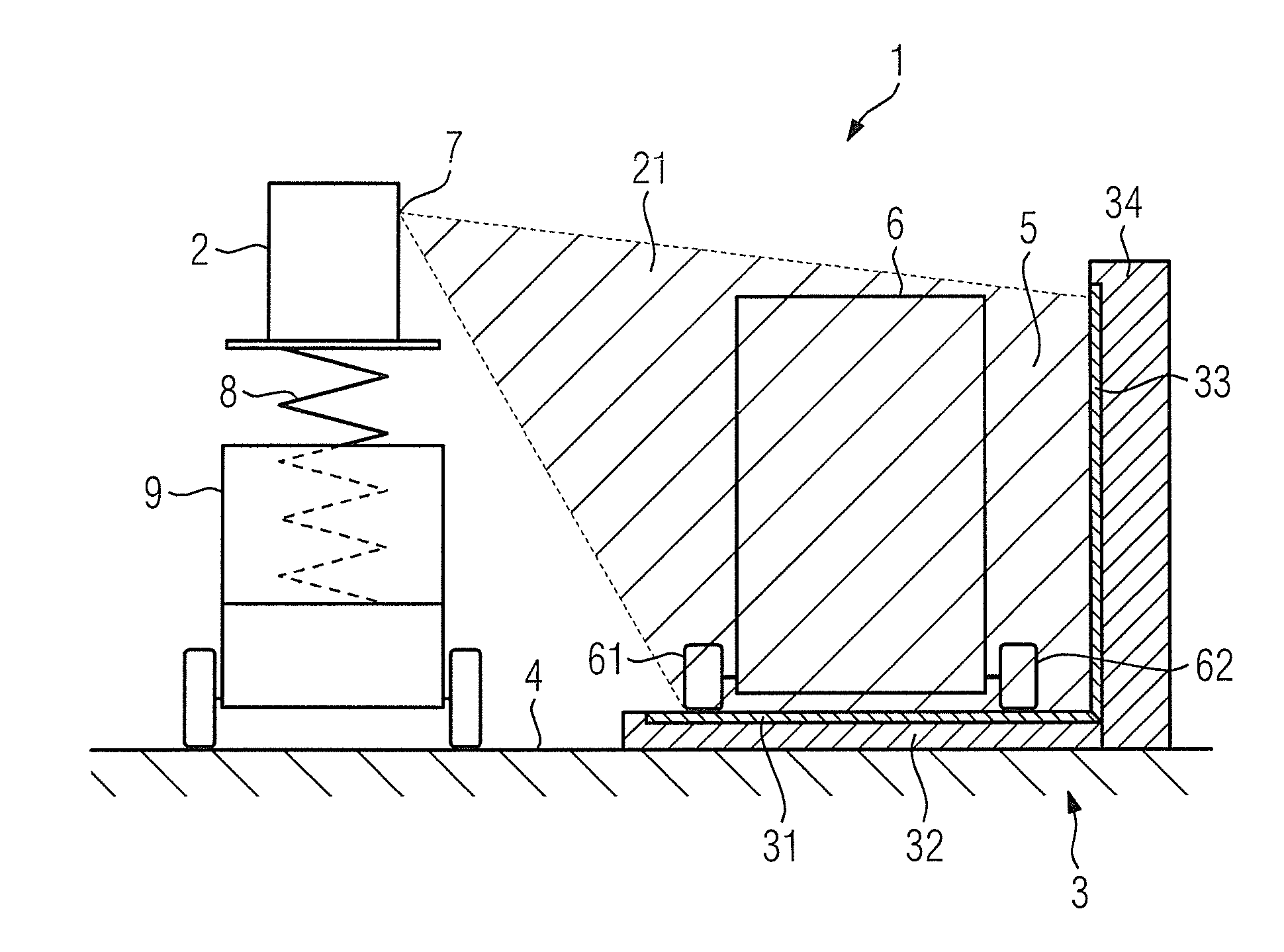
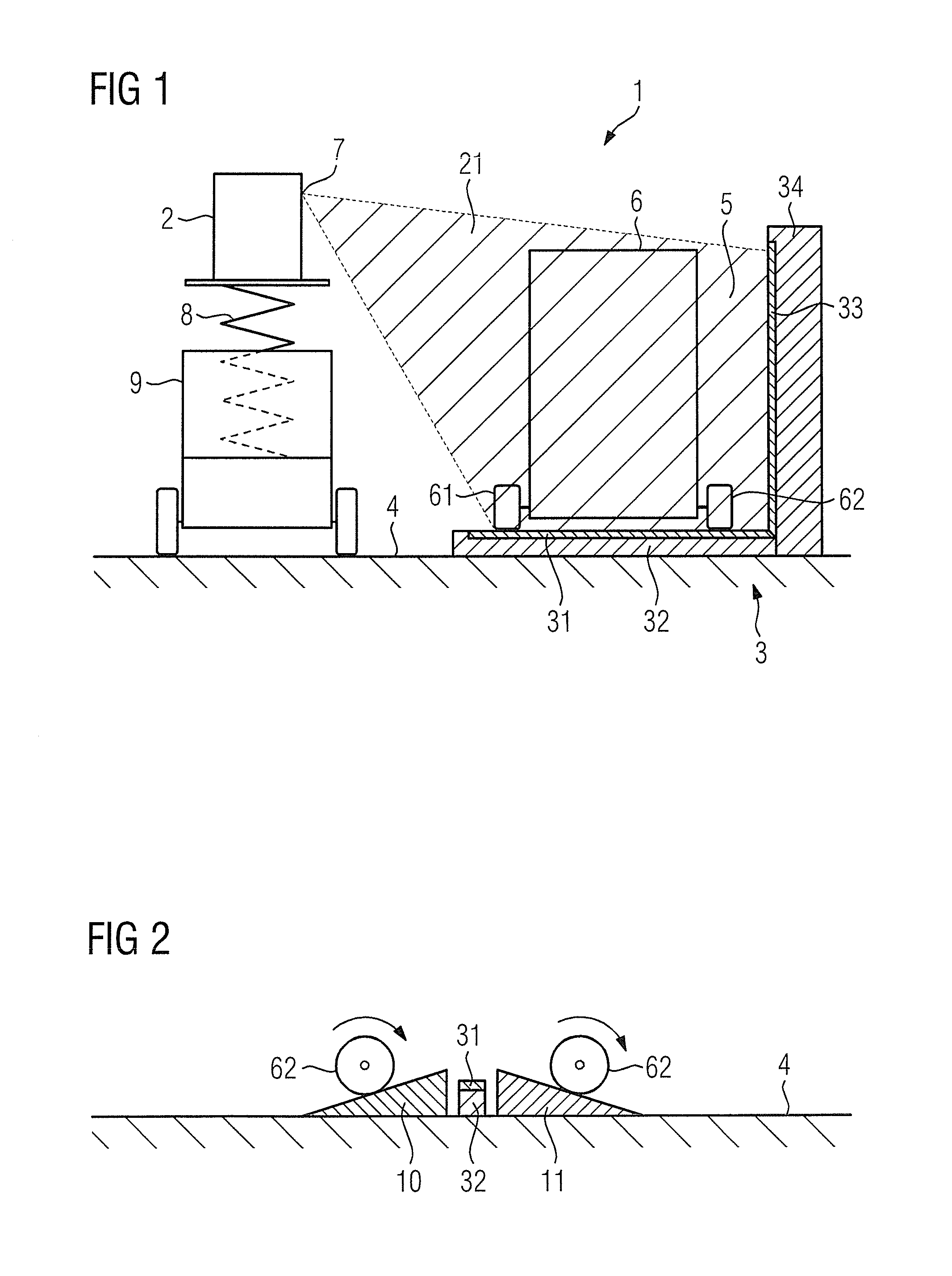
[0022]The embodiment of the inspection system according to the invention that is presented in FIG. 1 is executed as a mobile inspection system 1.

[0023]In the shown exemplary embodiment, the inspection system 1, that is shown in its operating position, has a radiation source 2 and an L-shaped radiation detector 3.

[0024]The radiation source 2 is designed as a LINAC (Linear Accelerator) and emits the radiation in the form of a radiation cone 21.

[0025]The radiation detector 3 has a horizontal detector surface 31 that is arranged in a horizontal support 32 that is placed on the floor 4 (roadway surface) in the operating position.

[0026]The radiation detector 3 furthermore has a vertical detector surface 33 that is arranged in a vertical support 34.

[0027]The horizontal support 32 and the vertical support 34 are arranged at right angles to one another. The horizontal detector surface 31 and the vertical detector surface 33 therefore form a detector gate 5 (“virtual gate”).

[0028]For implemen...


PUM

PropertyMeasurementUnit
radioscopy angleaaaaaaaaaa
weightaaaaaaaaaa
stabilityaaaaaaaaaa

Abstract

An inspection system has at least one radiation source and at least one L-shaped radiation detector for radioscopy of an article to be inspected. The radiation detector has a horizontal detector surface and a vertical detector surface and the radiation source is spaced apart from both detector surfaces. The inspection system is given a simple design by the horizontal detector surface running below the article being inspected and the radiation source being arranged in an upper corner position.

Description

BACKGROUND OF THE INVENTION[0001]1. Field of the Invention[0002]The invention concerns an inspection system.[0003]2. Description of the Prior Art[0004]An inspection system is known from FIGS. 20 and 27 of EP 1 635 169 B1. This known inspection system is designed as a mobile inspection system and is installed on a vehicle. The inspection system according to EP 1 635 169 B1 has at least one radiation source and at least one radiation detector (L-shaped during the inspection) for a fan-shaped radioscopy of an article [subject] to be inspected. The radiation detector possesses a vertical detector surface that is arranged in a vertical support and a horizontal detector surface that is arranged in a horizontal support. The radiation source is spaced apart from both detector surfaces.[0005]The horizontal detector surface travels over the article to be inspected, and the radiation source (which is executed as a LINAC; Linear Accelerator) is arranged such that it can pivot in a lower (floor-...

Claims


Application Information

Patent Timeline
Patent Type & Authority Applications(United States)
IPC IPC(8): G01N23/02
CPCG01V5/005
Inventor SCHMIDT, ROLAND
Owner SIEMENS AG
Why Eureka
Try Eureka