Double fed induction generator converter and method for suppressing transient in deactivation of crowbar circuit for grid fault ridethrough

a generator converter and induction technology, applied in the direction of motor/generator/converter stopper, dynamo-electric converter control, electric controller, etc., can solve the problem of affecting the ability to restart the regulated operation of the back-to-back converter, requiring complicated converter control switching, and rotor side converters and intermediate circuits are particularly susceptible to voltage transients

Active Publication Date: 2012-10-18
ROCKWELL AUTOMATION TECH
View PDF5 Cites 39 Cited by
  • Summary
  • Abstract
  • Description
  • Claims
  • Application Information

AI Technical Summary

Benefits of technology

[0011]A method is provided for operating a dual stage DFIG converter in accordance with further aspects of the disclosure. The method involves activating a protection circuit to connect a load to the DFIG rotor, as well as monitoring at least one stator current value and / or stator voltage while the protection circuit is activated. The method further includes determining one or more rotor converter outer loop regulator output preload values based at least partially on the stator current value, and preloading the value to a rotor outer loop regulator to begin regulation of the DFIG when the protection circuit is deactivated. Certain embodiments of the method also include selectively changing the sign of the stator current value or values when the protection circuit is activated in response to a grid voltage sag occurrence. In certain embodiments, moreover, the method includes selectively changing the signs of both d-axis and q-axis stator current values when the protection circuit is activated in response to a grid voltage sag occurrence, and determining d-axis and q-axis rotor outer loop regulator output preload values based at least partially on the d-axis and q-axis stator current values of the DFIG.

Problems solved by technology

However, the DFIG rotor voltages are consequently higher than the stator and grid voltages, and thus the rotor side converter and intermediate circuit are particularly susceptible to voltage transients caused by grid disturbances.
However, voltage spikes caused by crowbar deactivation can prevent or hinder the ability to restart regulated operation of the back-to-back converter.
This approach, however, requires complicated converter control switching.
This approach, however, requires extensive additional hardware and increases the cost and complexity of DFIG systems.

Method used


Image

  • Double fed induction generator converter and method for suppressing transient in deactivation of crowbar circuit for grid fault ridethrough
  • Double fed induction generator converter and method for suppressing transient in deactivation of crowbar circuit for grid fault ridethrough
  • Double fed induction generator converter and method for suppressing transient in deactivation of crowbar circuit for grid fault ridethrough

Examples


Embodiment Construction

[0020]Referring now to the figures, several embodiments or implementations of the present invention are hereinafter described in conjunction with the drawings, wherein like reference numerals are used to refer to like elements throughout, and wherein the various features are not necessarily drawn to scale.

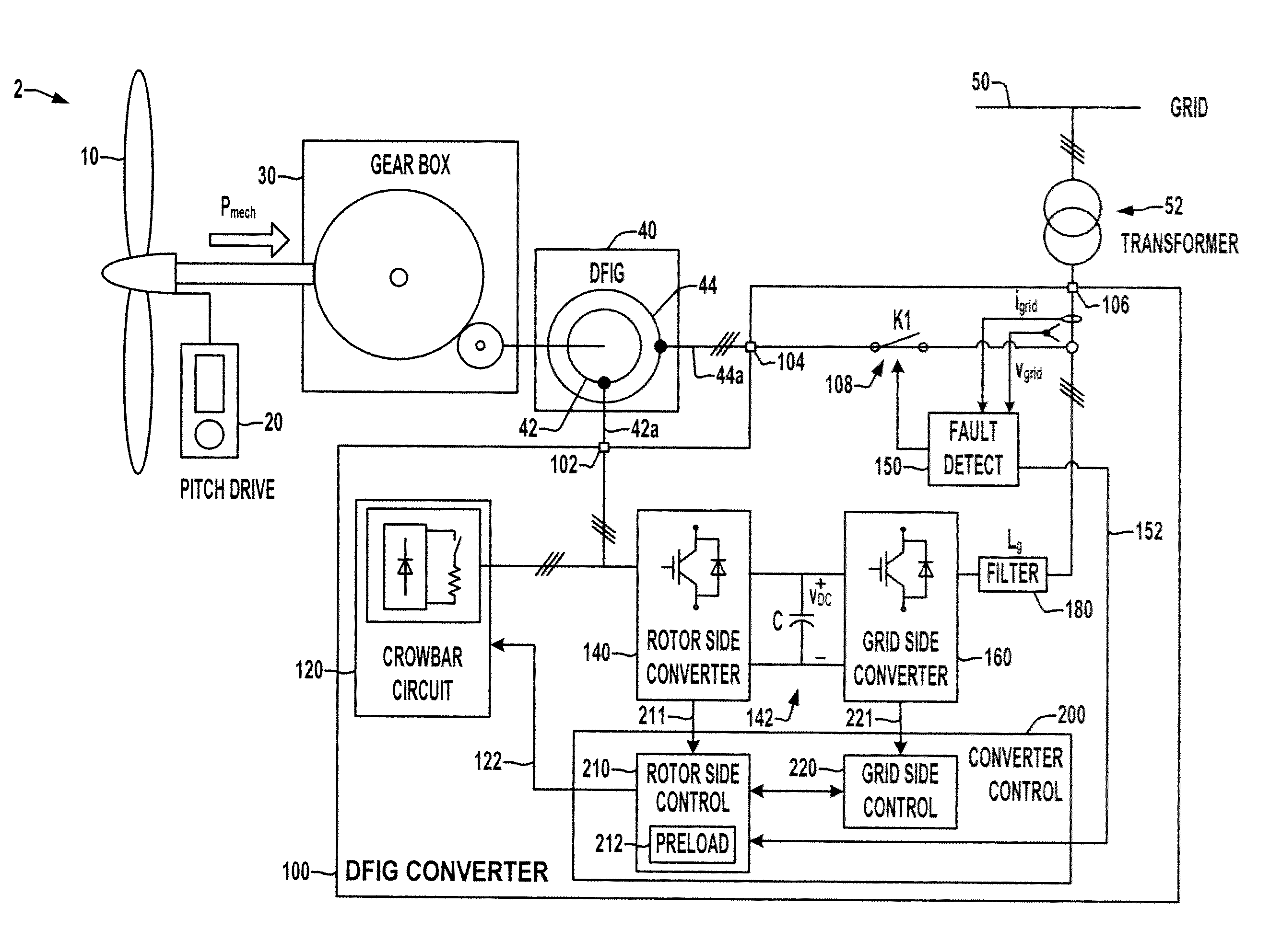
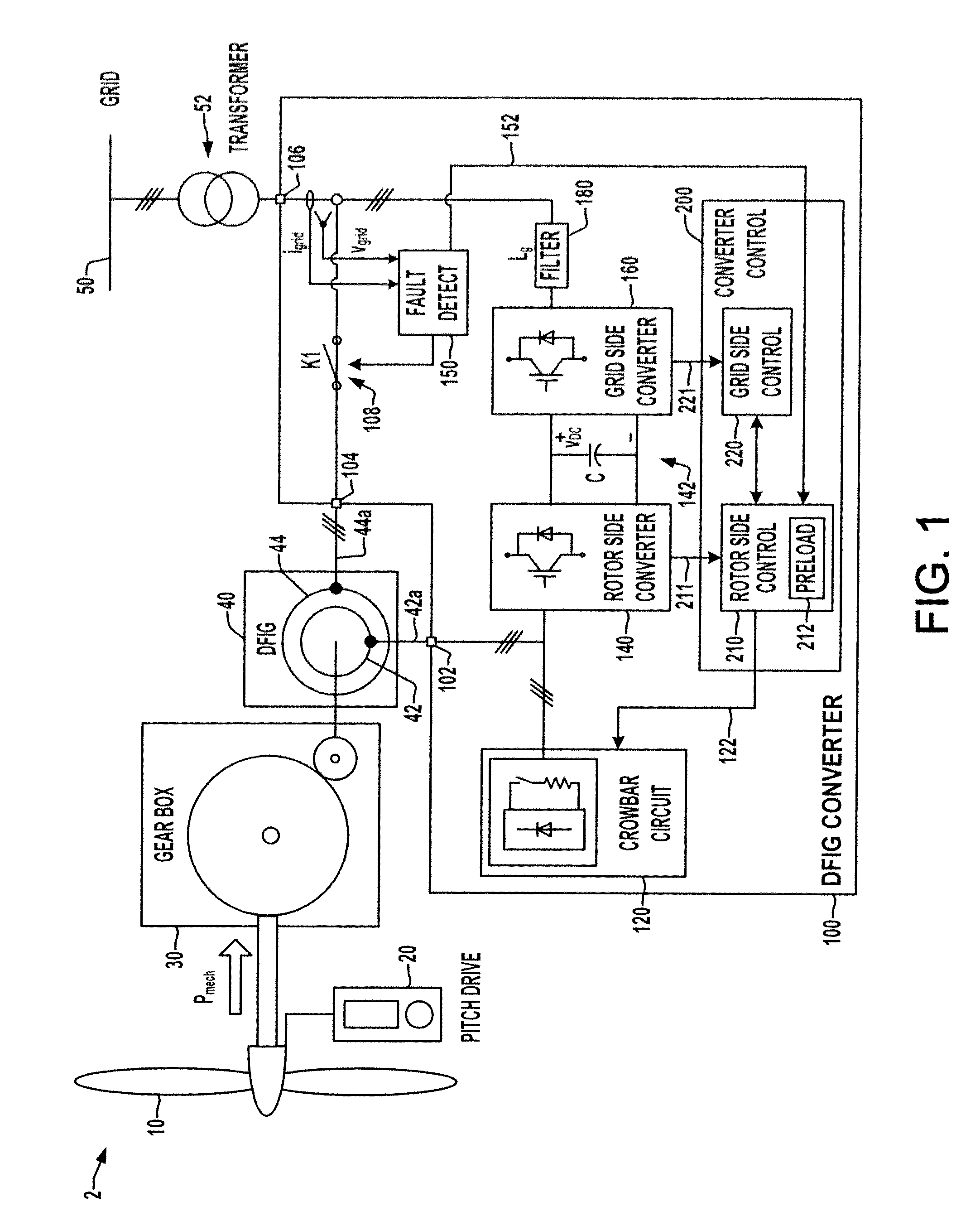
[0021]Referring initially to FIGS. 1-3, FIGS. 1 and 2 illustrate an exemplary wind energy converter (WEC) or wind energy system (WES) 2 with a double fed induction generator (DFIG) conversion system in accordance with various aspects of the present disclosure. The system 2 includes a turbine 10 with a pitch drive 20 providing rotational mechanical power Pmech to drive a gear box 30 with an output shaft mechanically coupled to a rotor 42 of a DFIG generator 40 with a stator 44. The rotor 42 provides rotor windings 42a (single or multi-phase) for transfer of AC power between the rotor 42 and a back-to-back DFIG converter 100. The stator 44 has windings 44a coupled to an AC grid 50 th...


PUM


Abstract

A double fed induction generator (DFIG) system and controller are presented in which the rotor side converter is preloaded with one or more initial values for resuming regulated operation to counteract transients upon deactivation of the crowbar protection circuit to provide grid fault ride through.

Description

BACKGROUND[0001]Wind energy systems are quickly becoming a popular form of power generation technology, and ongoing development is directed to providing wind-generated power to electrical grids. Power conversion systems are needed to adapt mechanical power generated by wind turbines to AC electric power in a form compatible with the grid. One type of conversion apparatus used in wind energy conversion systems (WECSs) is a double fed induction generator (DFIG) with a rotor driven by a turbine through a gearbox to supply power to a grid via stator connections. The DFIG rotor windings are connected to the grid via a back-to-back converter system having a rotor side converter connected between the rotor windings and a DC circuit, along with a grid side converter connected between the DC circuit and the grid. The system operates with the back-to-back converter drawing power from or supplying power to the rotor depending on the relationship of the rotor speed to the desired grid frequency...

Claims


Application Information

Patent Timeline
Patent Type & Authority Applications(United States)
IPC IPC(8): H02P9/10
CPCH02P9/10H02P9/007
Inventor LU, HAIHUIYUAN, ZHENHUANWEI, LIXIANGKERKMAN, RUSSELLUKASZEWSKI, RICHARDAHMED, AHMED MOHAMED SAYED
Owner ROCKWELL AUTOMATION TECH
Why Eureka
Try Eureka