Antenna apparatus for portable terminal

a portable terminal and antenna technology, applied in the field of antenna equipment, can solve the problems of restricted internal space and deterioration of antenna performance, and achieve the effects of improving the matching of built-in antennas, reducing noise, and reducing the performance of built-in antennas

Active Publication Date: 2012-10-18
SAMSUNG ELECTRONICS CO LTD
View PDF4 Cites 86 Cited by
  • Summary
  • Abstract
  • Description
  • Claims
  • Application Information

AI Technical Summary

Benefits of technology

[0011]In various embodiments of the present invention, the metal frame bolsters antenna performance instead of degrading performance of the built-in antenna, by acting as an additional radiating element, improving matching of the built-in antenna, radiating in an additional frequency band, and / or reducing noise.

Problems solved by technology

However, expanded functionality has required more electronic components, such that internal space is restricted.
Thus a design challenge for these devices is to find suitable space to package the added components, including the internal antenna(s), while maintaining the device slim, lightweight and small.
In general, a design challenge is to package an antenna of adequate length to meet requirements in today's small devices.
Further, recently a metal body provided for aesthetics has been constructed as part of a case frame forming an outward appearance of the terminal This metal body causes reflections of RF power and thereby is the cause of deteriorating performance of the antenna.

Method used


Image

  • Antenna apparatus for portable terminal
  • Antenna apparatus for portable terminal
  • Antenna apparatus for portable terminal

Examples


Embodiment Construction

[0018]Hereinafter, exemplary embodiments of the present invention will be described herein below with reference to the accompanying drawings. For the purposes of clarity and simplicity, well-known functions or constructions are not described in detail since they would obscure the invention in unnecessary detail. And, terms described below, which are defined considering functions in the present invention, can be different depending on user and operator's intention or practice. Therefore, the terms should be defined on the basis of the disclosure throughout this specification.

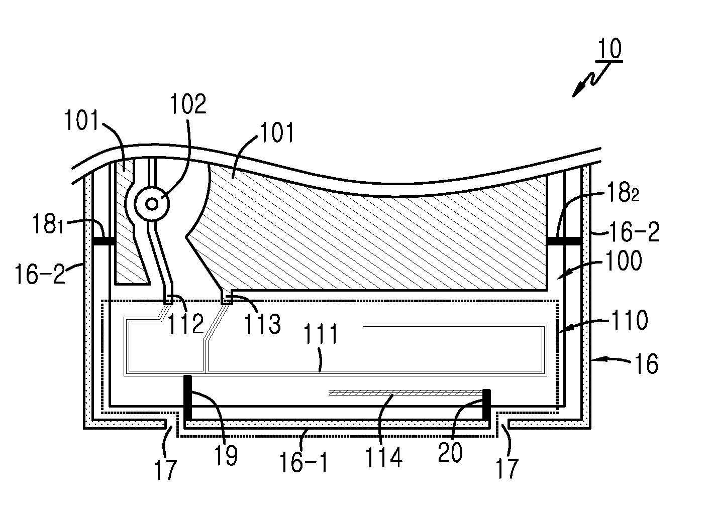
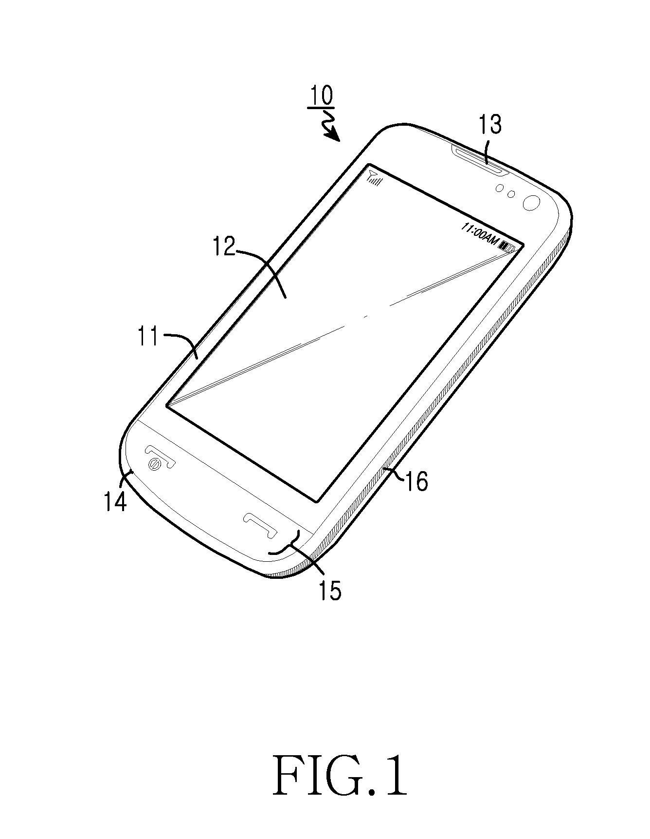
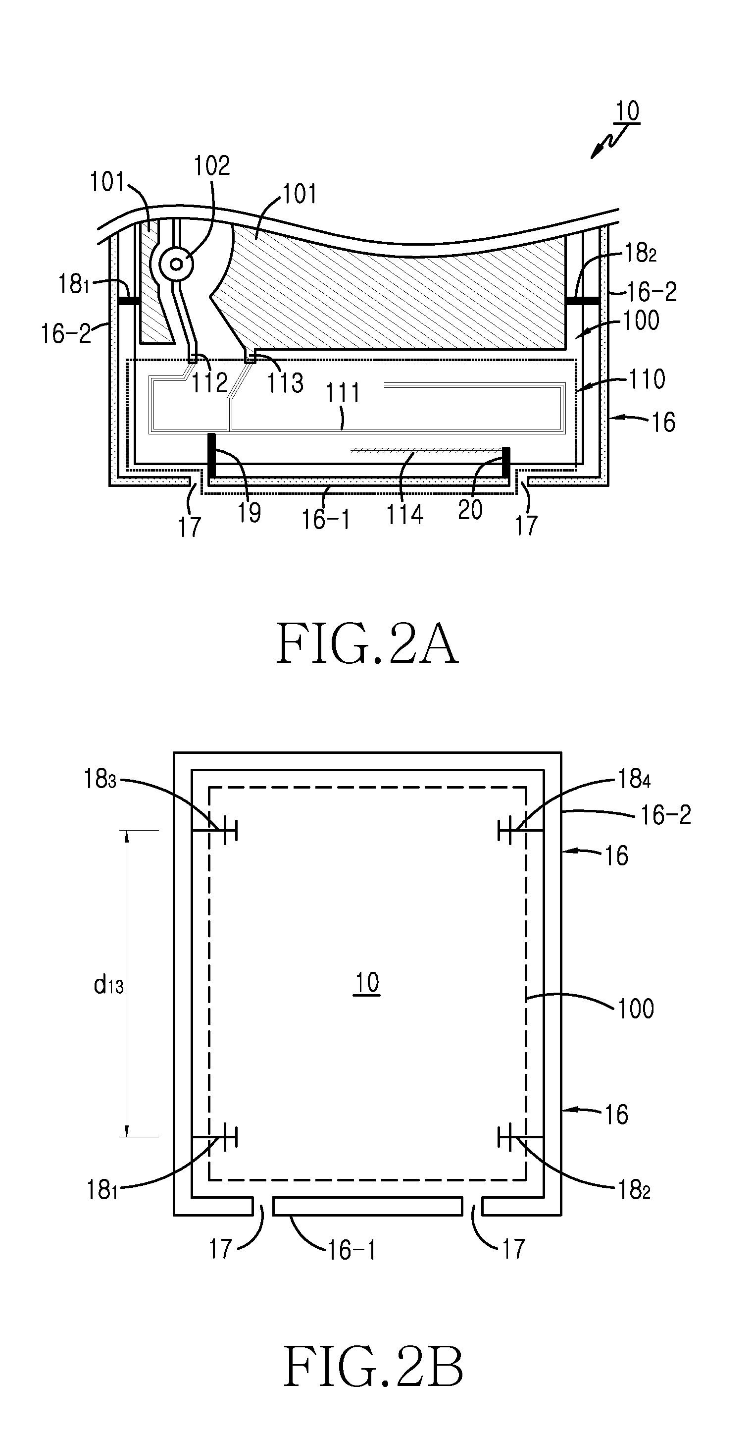
[0019]Briefly, the present invention relates to an antenna apparatus for a portable terminal in which a metal frame constructed as part of a case frame is realized as an antenna element that serves to enhance antenna performance rather than deteriorate performance of the internal antenna. The metal frame may have the additional purpose of enhancing aesthetics of the portable terminal. Also, the present invention ...


PUM


Abstract

An antenna apparatus for a portable terminal having a main board is provided. The antenna apparatus includes a main antenna that electrically connects to a feed line of the main board. A metal frame is constructed as part of a case frame forming an exterior of the portable terminal The metal frame is divided into first and second parts that are separated. The first part electrically connects to the main antenna or to the main board feed line, and is designed to radiate. The second part electrically connects to a ground surface of the main board. The metal frame enhances overall antenna performance rather than causing degradation through interference.

Description

CLAIM OF PRIORITY[0001]This application claims priority under 35 U.S.C. §119(a) to an application filed in the Korean Intellectual Property Office on Apr. 14, 2011 and assigned Serial No. 10-2011-0034548, the contents of which are herein incorporated by reference.BACKGROUND[0002]1. Technical Field[0003]The present disclosure relates to an antenna apparatus in a portable terminal[0004]2. Description of the Related Art[0005]At present, owing to the rapid advances in telecommunications, portable terminals such as cell phones, smart phones, PDAs, tablet and laptop PCs, and the like, are becoming a necessity to modern society.[0006]In recent years, the functionality of ordinary portable terminals has expanded, while the size and weight have been kept to a minimum. Slim, generally rectangular devices without protruding antennas have been popularized. In these devices, an internal antenna for voice communication, Internet access, etc. is deployed. However, expanded functionality has requir...

Claims


Application Information

Patent Timeline
Patent Type & Authority Applications(United States)
IPC IPC(8): H01Q1/24H01Q1/38
CPCH01Q1/243H01Q21/29H01Q21/28H01Q1/44H01Q1/24H01Q1/46H01Q1/48H01Q1/50
Inventor KIM, JAE-HEEBYUN, JOON-HOPARK, SE-HYUNLEE, DONG-HYUNKIM, AUSTIN
Owner SAMSUNG ELECTRONICS CO LTD
Why Eureka
Try Eureka