
Shape measurement device

a measurement device and shape technology, applied in the field of shape measurement devices, can solve problems such as the increase of installation man-hours

Active Publication Date: 2012-10-18
MITUTOYO CORP
View PDF5 Cites 17 Cited by
  • Summary
  • Abstract
  • Description
  • Claims
  • Application Information

AI Technical Summary

Benefits of technology

[0013]It is an object of the present invention to provide a shape measurement device including a probe capable of adjusting and changing the measurement range and the measurement accuracy.

Problems solved by technology

In order to prepare plural types of the probes only because desired measurement ranges (measurement accuracies) differ, enormous cost has occurred, and in addition, it has been necessary to perform an alignment operation and the like every time of exchanging the probe, resulting in an increase of installation man-hours.

Method used


Image

  • Shape measurement device
  • Shape measurement device
  • Shape measurement device

Examples


Embodiment Construction

[0029]A description is made of an embodiment of the present invention with reference to the drawings. However, the scope of the invention is not limited to the illustrated example.

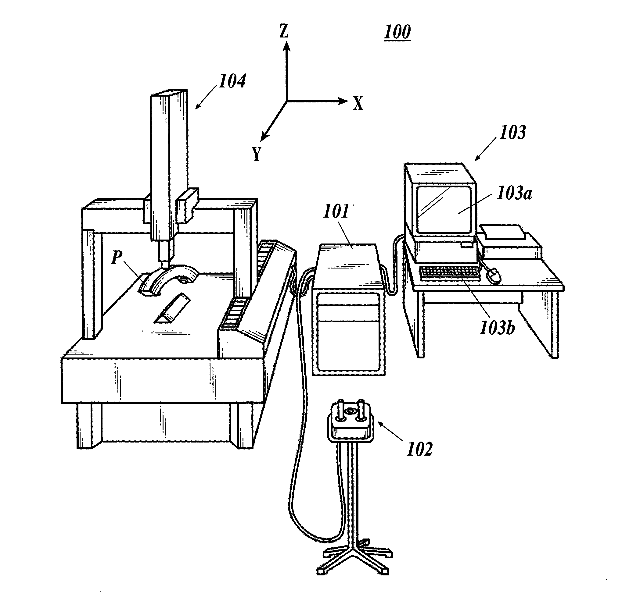
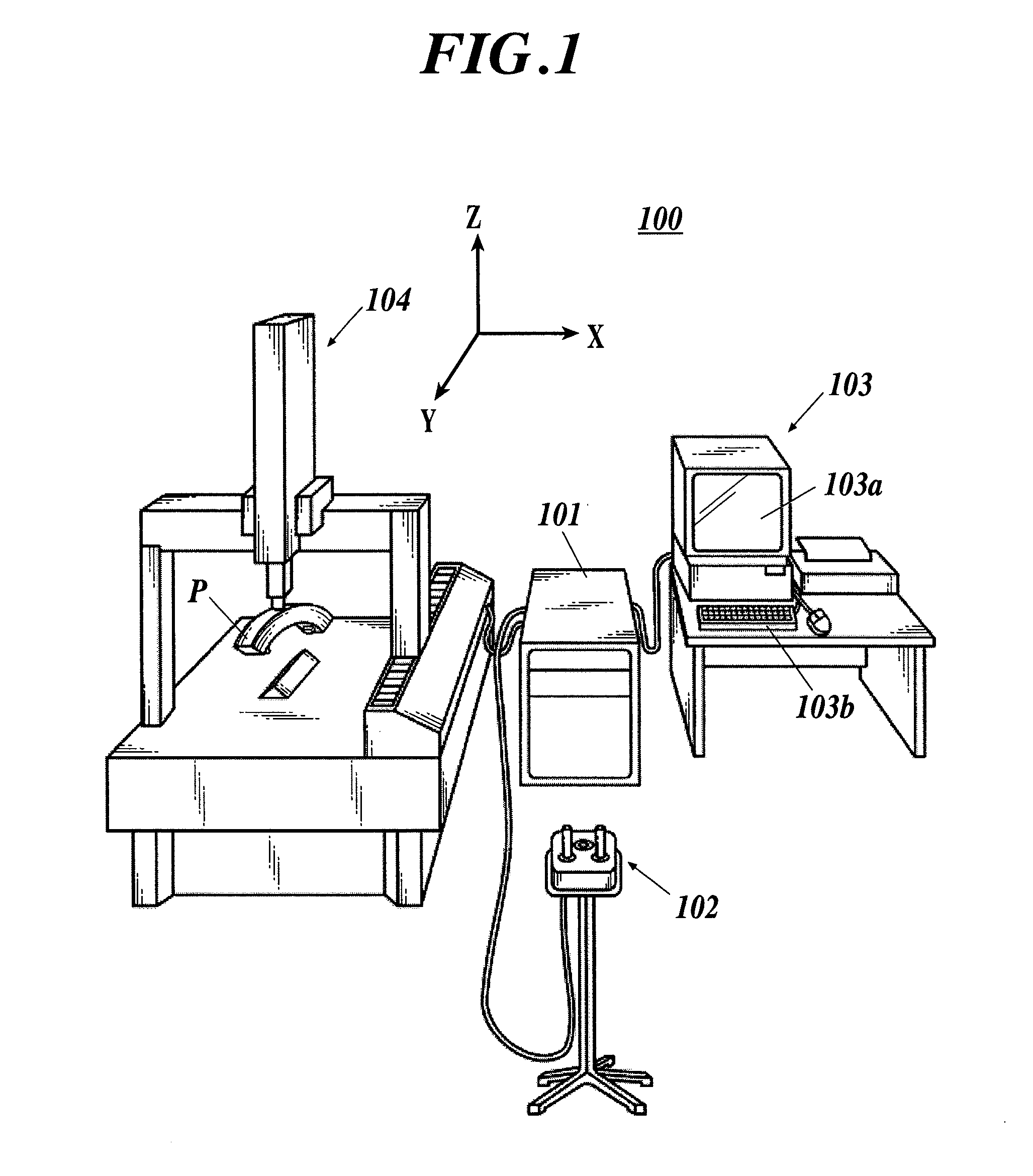
[0030]First, a description is made of a configuration.

[0031]As shown in FIG. 1, a shape measurement device 100 is composed by including a control device 101; an operation unit 102; a host system 103; and a device body unit 104.

[0032]The control device 101 controls drive of the device body unit 104, and captures necessary measurement coordinate value and the like from the device body unit 104.

[0033]The operation unit 102 is used for allowing a user to manually operate the device body unit 104 through the control device 101.

[0034]The host system 103 is composed by including: a display unit 103a that displays a variety of screens; an operation unit 103b that receives an operation designation from the user; a printer unit for performing printing on a sheet; and the like.

[0035]The display unit 103a is composed,...


PUM


Abstract

Disclosed is a shape measurement device including: a light irradiation unit which irradiates linear light onto a work; an imaging element which images reflected light reflected by the work; and an image-forming lens which forms an image of the reflected light reflected by the work on an imaging plane of the imaging element, and a light irradiation plane of the light irradiation unit, a principal plane including a principal point of the image-forming lens, and the imaging plane of the imaging element satisfy a Scheimpflug principle. The shape measurement device further includes: an image obtaining region selection unit which divides the imaging plane of the imaging element into a plurality of regions, and selects, as an image obtaining region, a region for use in measurement from the plurality of regions in response to at least one of measurement accuracy and a size of a measurement range.

Description

CROSS-REFERENCE TO RELATED APPLICATIONS[0001]This application is based upon and claims the benefit of priority from the prior Japanese Patent Application No. 2011-091731, filed on Apr. 18, 2011, the entire contents of which are incorporated herein by reference.BACKGROUND OF THE INVENTION[0002]1. Field of the Invention[0003]The present invention relates to a shape measurement device.[0004]2. Background Art[0005]Heretofore, a shape measurement device has been known, which scans a surface of a work, that is referred to as an object to be measured, by a probe in a noncontact manner, and measures a shape of the surface of the work (for example, refer to Japanese Translation of PCT International Application Publication No. JP-T-2009-534969).[0006]The probe is composed by including an imaging element such as a charge coupled device (CCD) and a complementary metal oxide semiconductor (CMOS), an image-forming lens, a line laser, and the like, and performs the measurement by using the Scheimp...

Claims


Application Information

Patent Timeline
Patent Type & Authority Applications(United States)
IPC IPC(8): G01B11/24
CPCG01B11/03G06T2207/30164G06T7/0057G01B11/2518G06T7/521
Inventor NEMOTO, KENTAROYAMAGATA, MASAOKIIWAMOTO, TADASHIMACHIDA, NOBUYOSHI
Owner MITUTOYO CORP
Learn More